This is not an “axiomatical” thing that if you use thicker cables the amperage will increase, because this is not a direct drive driver. Maybe if you use thicker cable the current will decrease. That was what I said before, when I have used good cells with low internal resistance, the current was at a lower level.
When I have used weaker cells with high internal resistance, the current increased (that means higher impedance in the circuit, same situation if you use thin Dmm cables)
It would be the best if the DMM self resistance (DMM+cables) would be equal with the switch resistance (less than 10mohm). A DMM self resistance often higher than 100-200mohm, so this is why we have to use thick cables. The DMM self resistance will never be 10 or less milliohm, but we have to try to decrease as much as we can.
Hard to tell, I think it will not increase the current, only stabilize (maybe it will eliminate the turbo mode).
It’s a little strange driver, but mine was well regulated with 2 TF flame.
No! I don't want to lose my "Turbo"! Anything but that! Maybe I need to add more resistance. :)
-Garry
Just a quick post, I’ve had chance to have a play today, I’ve also now seen turbo mode, on the meter at least but a rock solid 3.04a is hiding in this light.
Now, reflector IS plastic, what I’m thinking is that with this and the poor assembly, we’re on the second, poorer iteration, at least from manafont.
What I found today was the card board retainer was needed to keep the board in the pill, I’ve now built up a little solder and made the driver a good press fit. The pill was loose in the threads, its now tight recheck current at switch :-
1.94a high, .96a medium, .46a low. Rats, same as before.
Stripped out the switch board, eh? Why are the switch mounting posts anodized? Attacked the anodizing, recheck, 1.94a bugger! Test from switch to one of the screws, 1.94 glance away……glance back 3.04a! How the? Retest, 1.94, prod about 3.04a again. I’ve now reflowed the solder on the springs, reflowed the switch connections still can’t get 3 amps without using the meter probes. And I can’t even flash it on the wall without dropping back to 1.94a.
I think I need to find my m3 taps, retap the switch board screw holes to ensure there is no anodizing in them and replace the crappy counter sunk screws with decent brass m3 screws.
The tail cover screws look to be m2.5, I’ll have to dig around as I think I have some.
It’s frustrating because I know its in there, its not a hidden mode, just a crappy path some where in the circuit.
Pictures up later.
Awesome! I knew you'd find Turbo! Keep us updated on what you find that "fixes" it to maintain the "Turbo"!
-Garry
Well, the only things left in circuit are the switch, the switch board itself, the screws and the threads into the body. I’m slightly worried about it turning out to be the board itself tbh. ![]()
Can you do like CheapThrills (comment#177) and measure current with the body removed (cells held up against the driver/head)?
-Garry
With a bit of messing, yes I believe so, one cell would do it - we draw 3a off one cell in any decent c8/p60 xm-l. I’m less worried now, just had a shower and figured out how to build a copper switch sandwich. I just need a 5a reverse clicky to make it worthwhile.
Has anyone else that’s had a look in the pill considered that it could be filled in with a nice hunk of ally/copper. It sinks well into the head, but a nice big lump would help cooling, hell if you had a lathe, you could bore the face off, bore a press fit copper slug with a square mounting post. Direct bond a u3 to the copper post and solder in a 3mode sst-50 driver. 5a copper bonded xm-l u3 ala match could be interesting……
Ok, I see!
Thanks 8)
Reflector is plastic, I stand corrected, the plastic mold they use even has what looks like machining marks.
So it was always plastic that looked like alum?
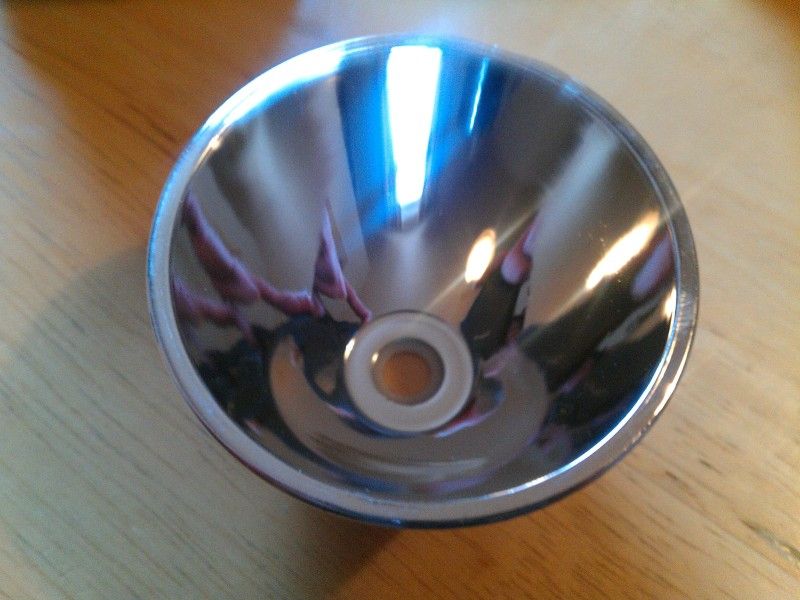
this is mine, aluminium:

<a href=Photo Storage target=_blank><img src=http://i185.photobucket.com/albums/x48/gords1001/IMAG0460-1.jpg border=0 alt=>
Not the best image, but notice the white plastic locating ring at the base. This reflector is plastic.
As I said above, possibly two iterations, there are certainly discrepancy’s.
Hmm... where did you two buy your T08 from?
Manafont. I’ll post everything up later, got tied up last night.
Tell me something, does the head unscrew here:
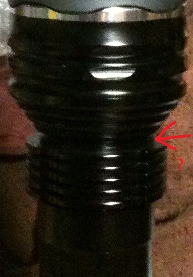
I can't get mine to unscrew here.
-Garry
I didn’t try too hard, but I doubt it - the pill extends from the base of the taper down all the way too the base of the fins.
So we can't access the emitter mounting? Or are people removing the bezel and reaching down from there? I was thinking to put the body in a vise and try cranking on it a little harder, but thought I'd ask first.
-Garry
Remove the head from the body, you can see two Ali rings and the driver, the inner ring is the pill. Mine was loose, I’d already removed the bezel, lense and reflector, there are no divets anywhere to aid removal, you could either pop out the driver and drill two 1/16th holes or just improvise.
There are a lot of threads, over an inch of the buggers. The pill unscrews from the body side of the head.
