Hannes modified one of our mutual friend’s Sky Ray 7xT6 with this mod as well. I couldn’t believe that the modified driver actually supplied 1.98A through the LEDs! This was the actual measurement through the LEDs. Tailcap amps was 4.8-4.9A with 2 x 26650’s.
The heat is handled surprising well. We compared the light with a Sky Ray 3800, Solarforce L2P and MPP-1 while keeping the 7xT6 on high. I’m guessing it was on high for 5mins and the flashlight was only slightly warm. We’ll to a temp test if anyone is interested.
Bro, is it 2 x 26650 (typo) or should it be 3 x 26650? It should be 3 x 26650 with ~ 5A at the tail. Then can you supply the LEDs with ~ 2A each, plus get 4800 lumens OTF.
Coz my TF X100 is already doing like 5.2 amps with 2 x 26650 TF Flames @ 4.2V.
I used Kingkong 26650s and they are the same, all good cells.
How do you open to get to the circuit? I just got a TR-j18, and it does not turn on. I think the circuit it broken. I have to upgrade. I can not get it to open. I already screw the lens off. I have tried to put the LED assembly off, but it does not want to come off. I have tried to screw it off(scratch the paint off) , and it does not want to come off…. Can you help?
I got a J18 on Monday. Didn't turn on either - was the switch. Took apart, cleaned up what I could, the switch itself was flaky. Funny, because now I can't get it to fail! Gonna check the amps - running 3 TF 26650 5000's, and see if I can spot that resistor to replace - I could probably get 0.05 ohm one from work. This thing looks super bright before any mods - ceiling bounce was ~450 lux, brighter than the FandyFire King clone.
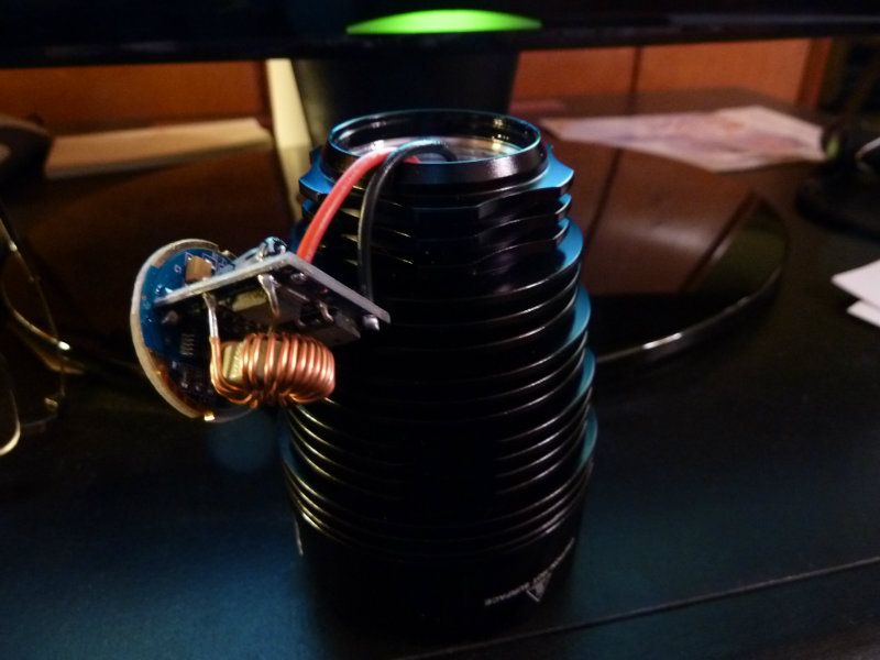
Total Bust... My J18 driver is totally different from Hannes'. I got the type with a perpendicular board mounted to the backside of the 26mm board. Also I'm seeing higher amps with 3 TF 5000's - I'm tailcap measuring 4A, then quickly dropping to 3A - no idea what's going on with the drop though. I know my DMM setup has been rock solid with custom 12 gauge leads, heavily soldered into banana plugs. Don't have the know-how to find the current resistor, so was depending on Hannes post up top.
Ohh, ok, both you guys (DayLighter and kingkong) have dim J18's. Been checking the other J18 threads...
DayLighter - I see you got an RMA from FastTech - so, still waiting for a replacement I guess? Sounds like it's been happening where 3 TF 5000's kill the driver... Wonder if there's a fix for that - maybe the driver I got is the new design? Hhhmmm...
kingkong - where/when did you get your J18? Hope my PM helped - interesting to see if your driver looks like mine.
according to WWEfans… he also have the same problem with 3 of his buyers… so they(Trustfires) send him new drivers.
he told me to ask fast tech for new driver … but why? they’re sending me a new replacement already without even waiting for the old one to arrive ( is that a awesome customer service or what?)
i guess this newer driver is buggy when using 3 26650s batteries. hopefully the replacement is not going to be a problem too.
Thank you for the instruction. Attached are picture of my TR-18. I am still trying to get to the driver. I got my TR-18 from CarpentryHero. I got the driver out following your instruction. Mine did not turn on after putting 3 -cells in.
Yes - that's the only configuration I've been using so far, but only used it in short bursts. No problems so far...
kingkong - from your picture of the battery end, the spring pictured there is mounted to the backside of the driver board. There are two tiny holes at the edge of that board - try poking/prying at them with something sharp, stainless steal preferred - mine popped out pretty easily. I have an assortment of tools such as these: dx-stainless-steel-diy-soldering-tools, but have other better stuff too. You could try ss tweezers, but maybe closed to avoid bending the tips. Mine wasn't soldered, but maybe yours is.
I know it's fairly common in these type of drivers, regulated, but don't use 7135's. I believe it can be found in drivers of all sizes. Hannes seems to understand these circuit designs very well but I guess hasn't been replying on this thread. There's been other postings/threads on guys doing the same exact thing to different drivers on smaller lights. Once you find the current sensing resistor, you can tweak it until you get the amps output you want (using a variable resistor pot or other means), then it's set. You can either replace a resistor or add one in parallel/serial, depending on what may be determined.
Got the I-O driver, installed it, wow! just wow! 3 simple modes, easy to install, fits perfect, sandwhiched in the thermal pads it came with between the 2 boards, cutting into pieces to fit. Measurements of the J18:
Before with 3 TF 26650 5000 batteries, as is, not fully charged but in the 4.05v range:
tailcap reading: 3.8A down to 3.1A, fluctuates, usually dropping steady
lumens: 3330 @start, 2940 @30 secs, throw: 34 kcd
After with same batteries as is, not charged in between:
tailcap reading: 5.78A
lumens: 4930 @start, 4726 @30 secs, throw: 48 kcd
Waiting on the TF batteries to charge, takes long on an i4, but should get 5000 lumens.