Will it work with 2x18650?
Yup, it even works with 1x18650, although there is a very slight decrease in output.
Hey Tom, mind taking some pictures of the insides?
I’m having some difficulty getting the driver out… or disassemble the head in the first place.
I’m not even sure where to twist, as it seems to be epoxied pretty well. ![]()
Sure! Wife's birthday today. gotta run to get her something  , hope can post some soon. For the head, I can't get past the lens. For the driver, they drill one hole on each side, opposite each other, of the + contact board, outside the brass ring. Once you do that, you can get more leverage (screw driver in the hole, applying force to pry it up, etc.), but I'm not sure about it being soldered or epoxied - mine looks like it was maybe soldered (don't know how they could have done that, unless it was done on my modded light later??).
Thanks for your reply! Take your time with the pictures, spend some time with your loved ones. ![]()
Drilling a hole in the driver board sounds slightly scary to me. ![]()
Although I’ll probably do that eventually, for now I’ll continue to pry it and try to loosen the threads on the head.
Cheers!
Good to know, thank you very much ![]()
I have another thoughts, would like to know if I’m right (know very little about this): lets say we have flashlight that works with 3 batts in parallel, 5A on HI. So, as far as I understand, if I insert 1 batt, it will work well if that batt is IMR o very good ICR, right (to provide 5A of current)? If I’ll try it with 2, it will be 2,5A per batt, right? (and 1,66A with 3). Thanks.
I'm pretty certain that's correct. The circuit, say, is designed to draw 5A. For batteries in parallel, the voltage remains the same (up tp 4.2v), so, it draws 5A and if there's 1, 2, or 3 batts, it should just split the load. I've been testing the 7G9 with just 1 battery to verify the amps drawn from the batteries. For 5A, single battery applications, you have to have a quality battery that can produce that amount of current for a period of time. With 3 batteries, it's not so crazy of a draw per battery and you get a longer run-time of course. The 7G9 is the same as the SRK in this respect (i.e. parallel wired batteries), though you are driving 3 LED's in an SRK. In a 2 or 3 cell serial battery setup (end to end), you add the voltages of the batteries, so for 2 batts, the voltage output can be up to 8.4 volts -- most of these drivers are designed for up to 9 volts I believe.
Thanks for clarifying that ![]()
![]()
Spot on Tom E - parallel batteries share the load, so that means less stress per battery (on high amp draws) and theoretically longer battery lives. Also there is less chance of mismatched Voltage problems, and no chance (I believe) of reverse charging … meaning (all things being equal) running batteries in parallel has less chances of catastrophic failure than batteries in series!
The main drawback is the apparent lack of ready-made high output drivers for “single” battery configurations, vs the many available for “in-series” configurations.
If I have time today I’ll try to drill a couple of holes in the positive contact plate and remove it, then put up some photos and any pertinent notes … that way we’ll see how to get into a factory-standard 7G9 from a novice modder’s (including me) point of view. I’ve already ruined the anodizing trying to remove the well-epoxied tailcap, so might as well bugger up the rest of the flashlight!
Oh, happy birthday to your wife Tom E! I think you should stay away from your flashlights for today at least … keep the missus happy ; )
Thanks! She read your post!!
Wife is on the phone with her mother, so got a chance to upload some pics. What d337944 is saying is right and it would be better from a stock light - mine already was modified, and since I didn't do the mod, I can only guess how it was done.
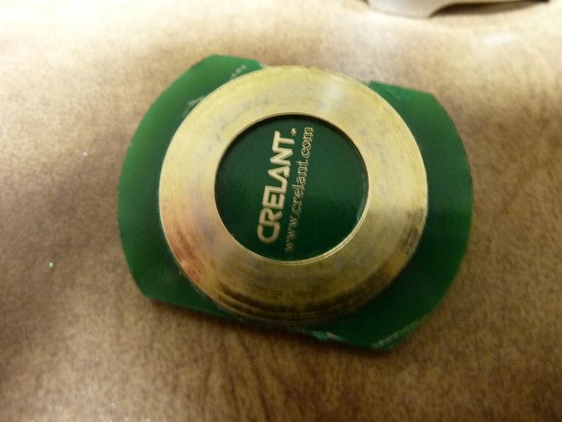
This is the + contact board, cutback as I described:
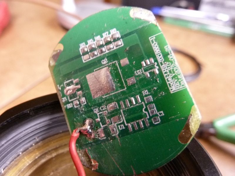
Here's the backside view with all the chips removed. Notice those 4 contact pts on the edge where it looks like it was soldered:
This is how it was wired up, after removing the duct tape:
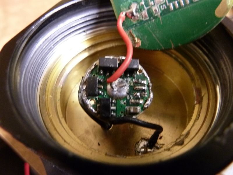
This is a view of the interior cavity. I added a brass pill, partially ground down for mounting the 17mm driver to. But you can notice the outer rim where the + contact board was soldered/glued/epoxied (don't know):
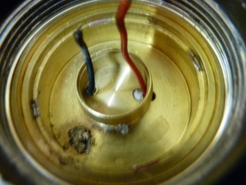
Full head view with the contact board out:
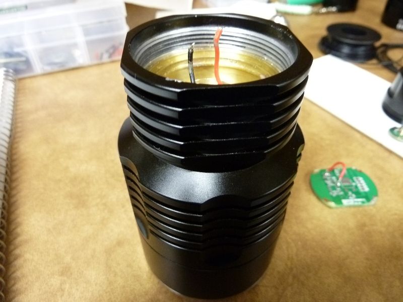
One more close-up view:
My plan is to mount the new driver, a Nanjg 2.8A plus 3 350's, total of 3.85A. Space is real tight for vertical clearance, but I measured then test fitted - seems like it will work. The + and - LED wires will be a tight squeeze in the reduced size brass pill, but I need the extras length on the wires in order to do the soldering inside the head assembly to the driver board. With the brass pill thermal epoxy'd to the brass base, then solder points added on the outside for electrical battery negative, this should give it a solid path for both thermal and electrical continuity.
Those blank brass pills have come in so handy on several light projects, I just ordered 10 more (5 for $3.50) from FancyFlashlights.com!!
Wow - thanks for your photos Tom E - shows us very well how the head is constructed! And … you didn’t get your wife another flashlight for her birthday did you? ![]()
I like what you’re planning mate, and how you’re using a brass pill for the holder.
I’ve just noticed that www.intl-outdoor.com are now stocking 4 Amp and 5 Amp drivers suitable for our needs … but I’m not sure whether they can fit into your brass pill.
I’ll open mine up when I get some time … and I reckon I’ll give the intl-outdoor drivers a try.
Keep us updated mate, and I’ll do the same when I can. ![]()
No, no flashlights for her, but there is one handy on just about every table or stand in the house! Well, she's not too happy bout that though...
I think Match's tests show going over 4 amps for a single XML won't help much though. Possibly the lumens curve vs. amps would look better on those new XM-L2's. I got a couple of XML2 T6's, but would love to put a XML2 U2 in the 7G9 - didn't order any yet, but planning to, probably from IlluminationSupply.com - he's got them. I can't see anyway of getting at the LED from the front - seems like the lens is impassable and though there is an embedded groove or ring little further down from the bezel, I can't see any joint in there - looked with a 10X glass. It's possible from the backend, that big brass piece unscrews if you can use a tool that applies pressure to the outside (reverse wrench?), maybe you can get enough bite on the brass and see if it will unscrew from the aluminum. Someone out there knows.....
You’re right about the max Amps there Tom - I reckon I’ll get the 4 Amp driver to be safe.
Also, we don’t really know how much current the standard switch will safely handle … 4 Amps “should” be okay I hope … safer than 5 Amps at least!
Cheers for now mate!
Thanks for the photos Tom!
Now if I just figure out how to get sucker open……
You reckon direct-drive would be too much for the LED? ![]()
Edit: Does anyone else have loose o-ring? When I twist the body to assemble the light, the o-ring becomes stretched and it gets caught…
Every annoying in my opinion, as it almost always happens when I replace batteries.

Hi Ryansoh
Direct Drive may work, but could also destroy the LED … it would be safer to use a small ohm resistor just to cut down the current a little. However the switch is also an unknown, as it may give too much resistance to make the Direct Drive worth while … or may even burn out / melt quickly!
Its a great flashlight though, and bumping up the Amps could turn this into a fantastic thrower!
Cheers
I don't think I ever had that o-ring problem, though it sounds/look familiar... not sure where. Direct drive with 3 parallel batteries sounds risky - not sure what that would result in.
Update for the Mod:
Using a Nanjg 2.8A driver with 3 extra 7135 350's, so 3.85A but measures 3.92A. It's working great now -- no more loss of brightness, but a normal small drop over 3 mins. The driver actually is the 2 mode set type with the UI that blinks at 5 secs in low, then you can switch mode sets -- really nice (lo/med/hi or lo/med/hi/strobe/sos). The vertical clearance is really tight - I under estimated the height of the board above the brass mount pill.
Now I'm regretting not adding 1 more (4.2A), but could still do that. Any more 7135's and I'll have clearance issues. Was thinking of drilling out the middle hole of the + contact driver board to clear the extra chips on top, but that could weaken the board.
Nobody responded about accessing the LED emitter on this beast, so think I'm on my own. Posted for Vinh on CPF the same question and still didn't respond after 2 days - I'll give him more time. I think I'll PM him. May also try Crelant, though I doubt they would help.
My relative crude attempt to measure lux for this 7G9 resulted in 64.5k, a mod'ed HD 2010 U3 @4.1A of 45.5k, XinTD C8 U3 @3.5A of 32.5k. Not sure how well calibrated my meter is but all readings were done at 1 meter.
Hey guys, I was able to access the driver area - I’ve put a post on CPF with some photos and notes … here’s a link to it:
Cheers
Hey guys, I’ve gotten my 7G9 to work direct drive!
It works perfectly with two 18650s to produce a much brighter output than standard, with output remaining stable and slowly dimming over time from the direct drive setup.
I’ve tried three 18650s simultaneously (and even tested IMRs VERY briefly!) but they produce too much current the the LED will start dimming after a few seconds due to heat! Though the 7G9 is heavy and chunky, the heatsinking could be much better due to the driver enclosure being a “hollow capsule” of air … maybe filling it with high-quality thermal compound would help, etc
Here’s the completed photo of the reassembled driver board … sorry it’s come out sideways, which is strange because it is the right way up on the picture hosting site! The board is very MESSY due to me running out of thermal glue and adding some regular epoxy, as well as the board toppling over during the curing process!

The photo of the internals sadly got corrupted for some friggin reason … but I can explain what I did:
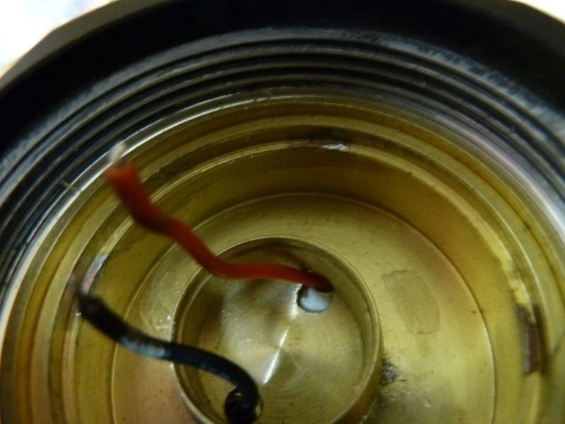
- Negative wire coming from the LED - I soldered directly onto the brass “chassis” in which the “driver chamber” is enclosed.
- Positive wire coming from the LED - I poked this through one of the initial drill holes (RHS of the “Crelant” wording on the board) and soldered it directly to the brass contact ring.
NOTE: The positive wire is actually UNDER the brass ring … the brass ring had come off the contact board “in transit” to me and was loose in the battery chamber when I received it! I ended up soldering and sandwiching the positive wire between the brass ring and the board, which worked out really well in the end!
I still could not open up the Head of the 7G9, otherwise I would swapped out the LED for an XM-L2 … or even and XP-G2 for amazing throw! As it is though, the output and throw are both MUCH better than standard, and without any modes to spoil the fun. ![]()
Cheers … feel free to PM me if you have any questions.
Whoohoo! Thanks for the update!
I can’t wait to get my hands on the internals… :bigsmile:
Hi Guys,
there is an offer on banggood for 78 usd… do you think is real or fake?
Many thanks
Ale