Maybe we could write a Wiki for how to do this? I have set up a page and done a rough draft. Since I've never actually gotten this to work (I think I need to buy a new clip, but maybe a new programmer as well) I won't be able to offer a lot of expertise.
Anybody can sign up at Flashlight Wiki for an account and then PM me to activate it so you can actually edit things:
Of course I can share the code. I have DropBox, but have not tried to share files before, so I have to try first.
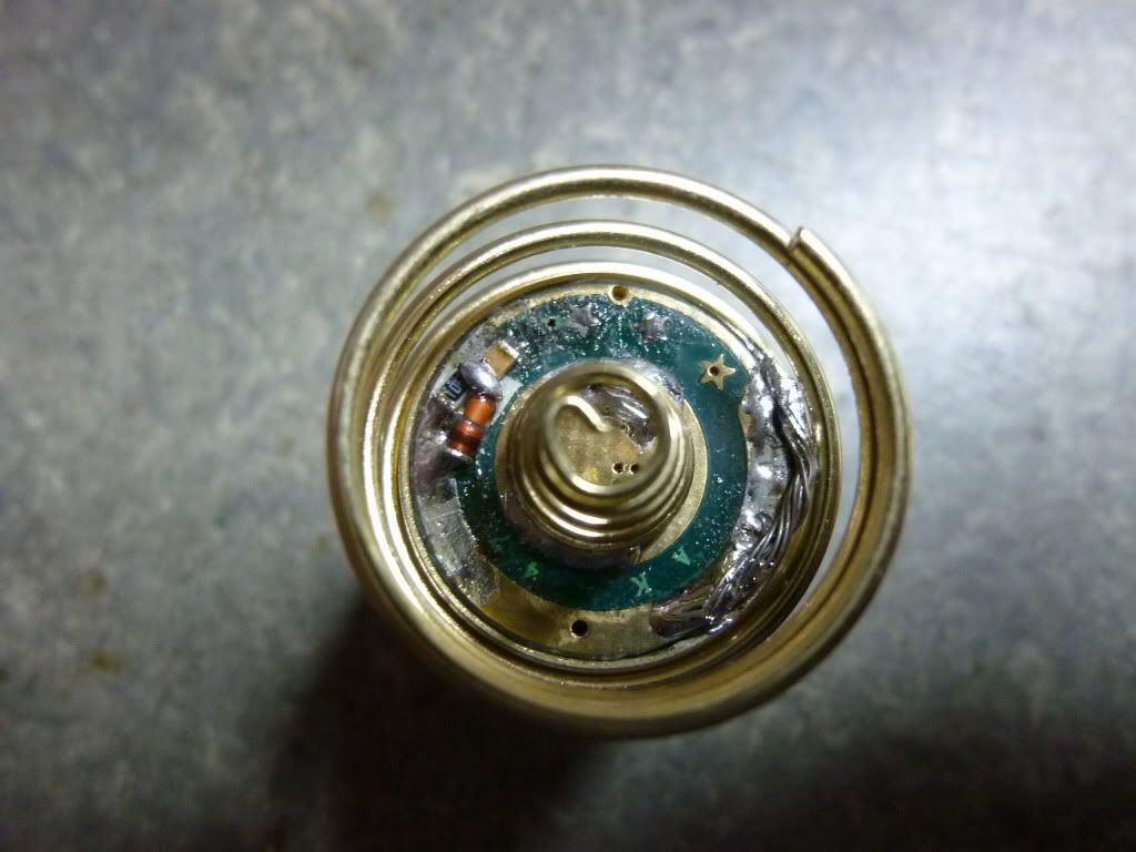
I use both kinds of memory that Tido's program support, memory after 2 sec on to remember the last used mode, but to distinguish tapping from longer_time_off I use memory_after_off which Tido calls "pin switching" because the function depends upon a capacitor connected to a pin of the MCU. At short "taps" the pin voltage is high, at longer "off" the voltage has bleeded away through a resistor. This function is discussed from post #166 onwards and calls for mounting 3 small components on the driver like this:
The 3 tap-detector components mounted on an AK47. Notice also how I connect the driver to the pill with a piece of multi-strand wire. I can then easily access the component side for re-programming by lifting the driver opposite the wire which is twistable.
I think it should take only a small modification to the program to avoid the additional components and use the 2 sec timing also for tap-detection. Of course the benefit of pin-switching will then be lost. I will try making such a version before sharing so it will take a while. But I will report back here when ready for sharing.
[EDIT]
Unfortunately it seems to be quite difficult to avoid having to add the 3 SMD components to the driver as the program code grows to be 48 bytes too big by omitting pin-switching. It think part of the programme has to be written in assembler to fit the available space of 1024 bytes.
For those still interested in my 8 mode driver with special memory and battery read-out I have made a zip-file here.
Thanks for sharing your code. I have an on STK500 dev kit with some spare Atmel 12 and Atmel 13. I can try to convert the code to assembly. I will need some help with the electronic..
is this clip sufficient? (12 dollars shipped) It looks like it has a nice small head for tight spaces, and it comes with a cable with a 10 pin female plug.
does this programmer look ok? (10 dollars shipped) It has a male 10 pin on the board, and the clip above has a 10 pin female. That should be a direct plug in right?
So with those 2 components in hand it comes down to software and the knowledge to do the programming? This is exciting!
Both those will work, they are both the cheapest (and most likely to break quickest) versions, but if you're going to flash a handful of drivers you probably don't need anything more expensive
.
However, it probably won't be a direct connection; you will need to change which pin on the clip each wire from the programmer connects to. To do this, find the pinout of the programmer (all similar AVR programmers will have the same pinout) and match it to the pinout of the attiny13 (and hence the clip). Depending on how the wires are connected to the clip you might need to desolder/solder but someone who’s done this already can better advise.
Welcome to BLF, Benik3! From those pictures I can't tell for sure whether it is an Atmel chip or not. My guess is that it is not. But I have never gotten that driver.
i´m new in this forum and i would like to ask which programmer tido is using or which one is the best bang for the buck. most of the time it would be used for attiny 13 and atmega 8 programming.
check post #266 for cheap programmer and clip. I bought both of them a couple of days ago and will take pictures and let you guys know how the clip fits when they come.
What you want to do is both straight forward - and not!
You have to modify the file driver.c in Tido's package BLF-VLD-0.4.zip
The first thing to do is define the 4 modes and insert them in the setup:
line #39:
#define NUM_MODES 4 // how many modes should the flashlight have (1-5)
line #192-193:
// initial mode programming, indices to modelines in the following array
0x05, 0x06, 0x07, 0x08, 0x00, // your levels are at index 5,6,7,8
line #108 (activate nomemory as you don't want to have memory):
#define NOMEMORY
The function should now be:
1. The light will allways start in 4% mode.
2. A short tap on the switch will switch to next mode, but if the light has been in a mode for more than 2 sec it is necessary to start the timing first by tapping once. (This can be avoided by using what is called pin-switch in the program, but this demands the mounting of 3 components on the driver).
The file should now be compiled from the SIMPLE directory (after unfolding BLF-VLD-0.4.zip).
It will be necessary to have AVC compiler installed, look for this elsewhere in the thread. Furthermore you must have the programming equipment which can be hard to get running (bad connections) and of course a driver with Atmel ATtiny13.
I can have overlooked something so I can give no guarantee that this will work, but good luck.

 But if the ATMEL is some and the connection is some we could use your program.