matt, indeed, your explanation clarified what you meant. :)
My tightly wrapped P60 dropins have good heat transfer. They get warm as fast as my UF980L with a screw-in pill design. The force comes from a very tight fit..?^^
P60 has its disadvantages, but they are interchangeable. The C8 isnt, there are so many manufacturers and they dont all use the same threading..
DBC, you obviously didnt read matts post two posts over mine. Thats where he mentioned the C8 and thats what I answered to. Next you show some great threads (which have nothing to do with most crappy C8 threads at which my post was directed) and tell me there wont be much air inbetween, which is pretty obvious.
Thingy was not meant offensive, its just a neat small light. Neat thingy is a compliment in German. ;) I hope we will see a thread about your neat thingy once its done.
The EDC+ dropin is also a neat thing but no challenge for a P60 host. 2A is safe even for very long runs.
I did indeed read the initial reply from Matt, and understood your explanation as the why concerning C8 threads. Being fairly new to the forum, I have yet to master following multiple conversations within a thread and usually try to keep the OP in mind. Doesn’t help getting old and forgetful.
Y’all will definately see more on my “lil thingy” when it’s done. Looking for ~300 lumens or more from this pinky sized little dynamo, we’ll see how that works out.
And yes, the EDC+ is a bit on the conservative side. For some reason my DMM won’t get a Hi reading at the tail, but Med is 1A and Lo is .03A. Nice build, like what they did with the copper body and silver plating, very useful drop-in for some down-and-dirty illumination during macro photography. I plan on getting one that will be quite different, already have the host built, that Matt is working on over in Australia. I’m thinking it won’t be quite so tame, as he advised me to upgrade the switch in my host so it wouldn’t be melted down with his drop-in ![]()
Skyrider, are you looking for more output than you’re seeing in readily available drop-ins, or are you primarily interested in the DIY project?
I think the interchangeability is its biggest advantage, which also leads to another big advantage - the relatively loose tolerances manufacturers can get away with and it still manages to work. Given the difficulty manufacturers seem to have just getting the bore size right, I shudder to think what the outcome would be when you throw threading in there. I guess in the real world, ease/ cost of manufacture trumps all ![]()
DBC, yes, multiple conversations in one thread can be a downside in such a low-regulated forum like this. But I really enjoy it. Thats why I usually start my posts with the name of the one I'm adressing my post (or parts of it) at. :)
matt, yep, definitely. Even Solarforce hosts have different head IDs..
You stated in your first post that ” I will solder 3 very small pieces of rectangular pads on top for bonding the LEDs.” That won’t work, will it? The pads have to be isolated from the heatsink or they’d be a direct short. Soldering them in place isn’t an option, is it? Am I missing something here?
Edit: I see it now. Soldering a pad for the center of the emitter to be bonded directly through copper to the copper heatsink will raise the electrical connections and prevent the contact that I thought would short them out. Will you, then, connect the wires at the top of the emitter?
Solarforce is not consistent?
<—hand over mouth, frantically checking the 3 in front of me while worrying about the P1d the wife has. ![]()
I have an L2P and an L2T and they are off by a few tenths of a mm. Also, the inside of the L2T is not as smooth as the inside of the L2P.
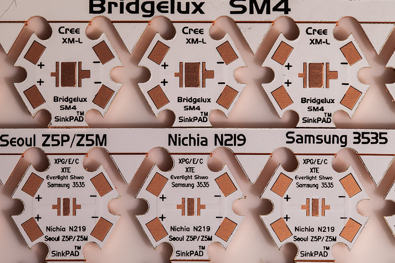
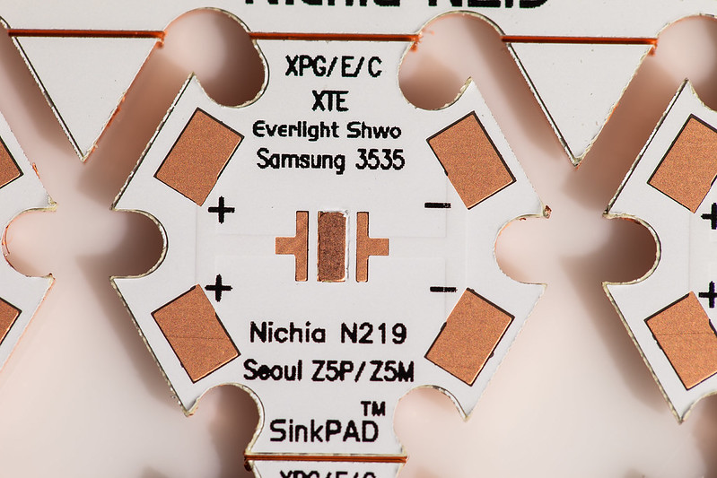
The Nichia does not have solder pads on top btw. So if you want to raise it, soldering wires will be hard. I would rather use three 10mm stars. That would work.
Skyrider, I just got 20mm SinkPads and I’ll be attempting to turn some of them down. Will let you know how that goes. You’re looking for a single XM-L, correct? My main project here is an XP-G so I may just attempt the XM-L to 16mm and get a feel for it, before going for 10mm on the xp-g.
If I’m successful in turning down this XM-L copper star down to 16mm, you want it? I got 5 boards in XM-L and 10 for Nichia, XP-G.
Nightcrawl, anything I should know before I attempt resizing these?
Will be taking some pics first, I’ll post em a bit later.
Yes, copper is pretty hard to grind down compared to Aluminium. Dont let it get too hot.. and when you are done, check for connection between the center pad and the positive and negative pads with a DMM.
Thanks NightCrawl, I’m looking for there to not be a connection between the center pad and either led connection, is that correct? Making sure I haven’t shorted a lead against the board, right?
! !
!
! !
!
! !
!
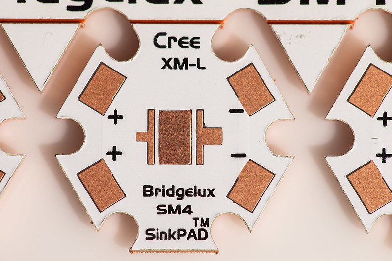
These can be seen in much higher res by clicking on the pic and then viewing the original in Flickr.
Just got back from class and looks like you guys had some good discussion going on haha. Ideally I wanted to start this build ASAP but will probably have to wait til may to start.
Yea, the idea is to raise the LED so I still have access to the bottom contacts. I’ll use a method mentioned in OLs thread about making stars to gain access to the contacts with copper pads.
Let me know how the turning down the 20mm star goes. Sounds like it could work out. I only worry about the +/- contacts making contact with the pill if I were to install it in the p60 drop in. Is it possible to grind off part of the outside of the contact so that it stays fairly physically isolated? Hold on to your sinkpads for now as you will probably have better use for it. Ideally I wanted to start this build ASAP but will probably have to wait til may to start and the 16mm sinkpads might be out by then.
I mainly want to make these builds because there isn’t a drop in currently that fits what I want.
For the XML I want:
- XML-2 T6 3C
- Direct copper bonding (reduce thermal sag)
- Some extra mass/better heatsinking (reduce thermal sag)
DrJones Lupodrv driver
For the triple:
- 3x nichia219
- triple driven with 1 amp to each led
- direct copper bond
- DrJones Lupodrv driver
Yes DBC, you wont want a short. ;) I hope you have a DMM.
I have grinded down a lot of PCBs until today and it is really easy. If you look closely at the boards you will see a thin "bump" connecting all the negative solder pads on the one side and all the positive solder pads on the other side. Thats just a trace with paint on it, so you can scrape off the paint and solder to the thin part.
Now if you want to grind down the board to 16mm for example, the edge will be right in the middle of the soldering pads. Thats usually no problem, but if it turns out to be a problem I use my dremel and a thin cutting disc to grind off the solder pad or trace. The dielectric underneath is a lot thicker, so its an easy operation.
Seems like an Xacto knife could be used to trim the pad back so that it would clear the edge, and/or a bevel put on the top side to also ensure no contact with the sides of the pill.
Now I am interested in some.
DBCstm, if you have the tools to turn it down could you do that for me? Send me a PM if you can with your paypal addy!
Just thought of something, why don’t people solder stars into pills instead of using thermal paste. Is it just the difficulty in heating up a whole pill to melt the solder?
Also, when people “lap” metals together to get the best surface on surface contact, what is the exact process people use?
People solder stars to pills. Its just that you cant easily solder most stars because they are made of aluminium. Copper stars widely available are rather new on the US market..
Lapping is basically the next step after grinding.
There are a lot of video tutorials if you need something visual, just search for "cpu lapping".
But to put it short: first step is to grind star and heatsink flat. Glass tables or something else you know is REALLY flat and even are great for that. Put the sandpaper on it and start grinding. If you go back and forth, left to right, make circles or perform weird figures doesnt really matter imo. I usually use 400 grit sandpaper to start with. After that I go up to 600, 800, 1000, 1500, 2000 and 2500. After working star and heatsink with 2500 grit sandpaper, you will have a mirror finish. That will already make a REALLY good connection (you should also do this if you want to solder it all together, because the thinner the solder layer, the better the heat transfer is).
Now if you are really bored after that, you may polish and or lap the surfaces. I guess polishing is clear, just use some polishing stuff and do star and heatsink. To lap, you rub star and heatsink together with lapping compound. Grinding and polishing is basically just making the surface very smooth. Lapping will also make it more even because the grinding particles are not fixed (like on sandpaper where they take material off the surface) but "float" around and "compress" the surface.. not that easy to explain. Both will improve the surface quality..
But I have to say that polishing and lapping are not as easy/fast as grinding and wont have an effect as big as grinding has. I did it once and decided that its not worth the effort. Two reasons for that:
-aluminium stars: heat transfer is not good enough for lapping to have a significant influence
-copper stars: heat transfer is good enough with solder between star and pill for lapping not to have significant influence
Thanks! That was very clear. Looks like if I decide to use a copper star I’ll grind flat/solder them.
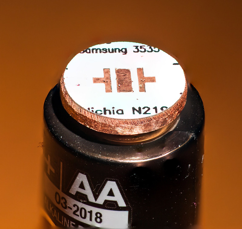
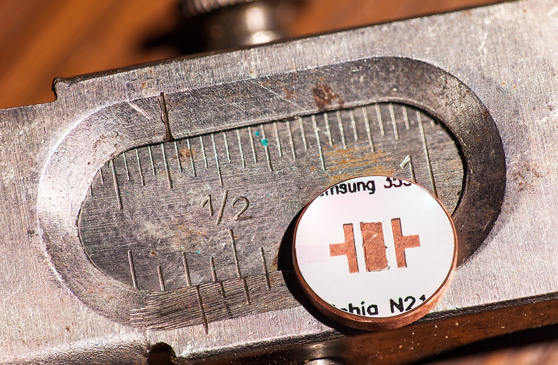
My very first attempt at modifying a MCPCB. Needed 10mm. Found 20mm. Makita cordless and Dremel make all things possible, well, and JBWeld. ![]()
! !
!
Nice! That looks pretty clean. How did you go about making sure the center pad was perfectly centered?
That was the hard part. I used a 1/2” 6061 bar to mount in my cordless drill. JB Welded the star to the bar. Very quickly, (the JBWeld sets up in 5 minutes) I made adjustments to the centering by laying the drill on it’s side and holding a pencil to make a circle on the turning star. If the circle showed the pad centered, I was good. Took 3 attempts to get it just right before the JB Weld set up.
Then I used a cutoff wheel on my dremel tool to make the initial cut for size, filed it to get it where you see it now. Then found out that 11mm wouldn’t fit in my Light Engine. So filed it more to get it exactly 10mm and polished the edge smooth with sandpaper, finishing with 600 grit. Used the 600 grit to cut a bevel to ensure the traces were away from the copper Light Engine.
The calipers in this picture belonged to a late Uncle who passed away back in the late 30’s. They’re something like 100 years old. I’ll get a couple of holes drilled through this one for the wires tomorrow and then I’ll get your XM-L pad turned to 16mm. That one will be a piece o cake compared to this one…or so I hope! Tested it out with the DMM and all systems are go. ![]()
! !
!