Well here's a tune by the Real King
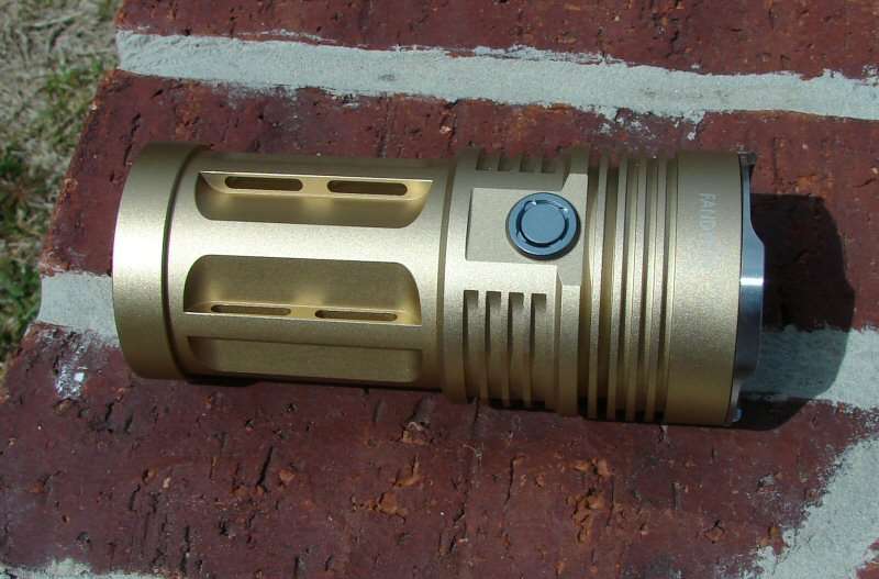
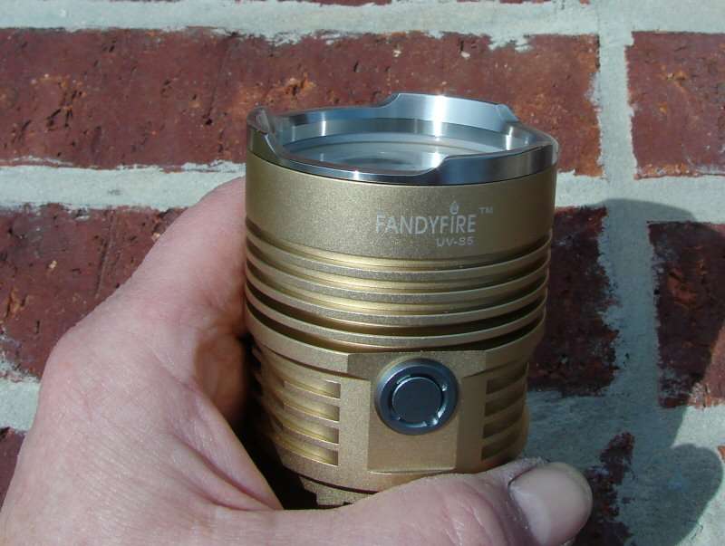
So I went ahead and bought one of these FandyFire clone kings about a week before the Black Kings dropped in price. Damn, I'm singin the Blues over that!
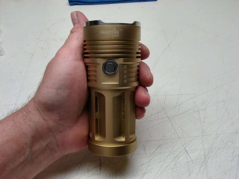
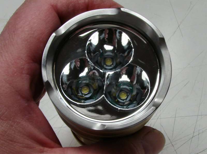
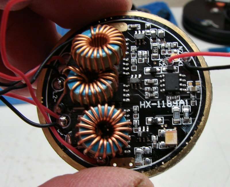
For the price, I guess it's ok, but the threads were bone dry. The reflector looks like it never got final finish before plating and one of the LEDs has a scuff mark on it, so I'm not too happy.
Time to rip it apart.
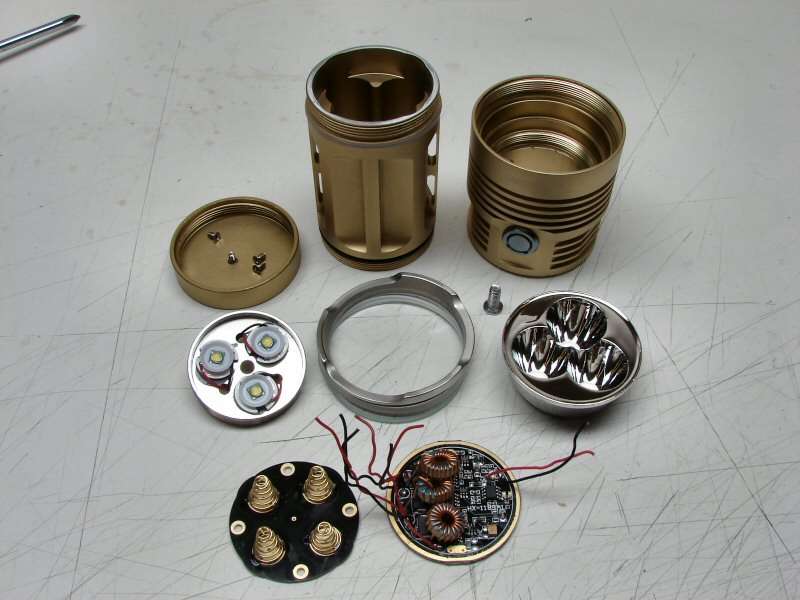
Well, that made me feel better.... I will be keeping the outer body, head and tail cap. LOL.
I am going to turn this into a O-L NiMHKing. EDIT: Four 4/3AF NiMH batteries in series, with Three NANJG 3040mA drivers in Master/Slave configuration. I may put in Three XM-L2 leds in it. I am not sure yet. I may keep the stock reflector, but it's so ugly (how ugly is it?), It's so ugly I had to slap it when it looked at me. Ok, so I'm not a comedian. I will either stipple the stock reflector or put in Three of something - small reflectors or TIR optics. I am not sure yet.
I have a lot of work to do...
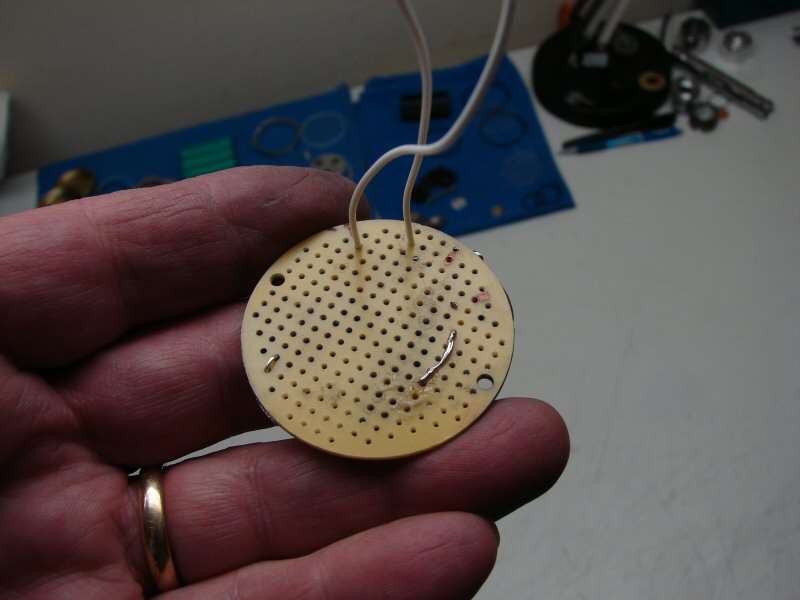
Radio Shack has what you need. I had some of these round boards from another mod and guess what. This one will just about fit perfect and will replace the driver board that was in the light.
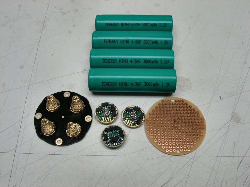
Here's where I start. I have to make the board on the right into a contact plate for series use. I have to rework the original bottom plate for series use. I have the three drivers and the Master is a DrJones reprogrammed one. That means it's going to have a Great UI.!
Did I say I have a lot of work to do?
--------------------------------------------------------------------------------------------------------
I have managed to do a little work today.
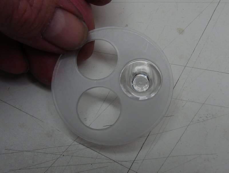
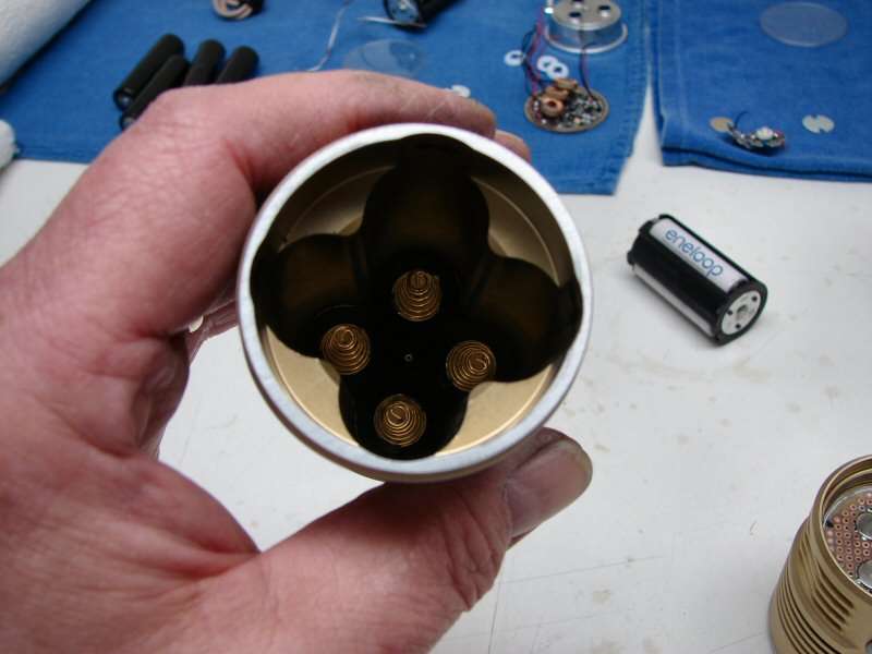
I have decided to go with the TIR optics. I already had a locator plate, from a failed project.
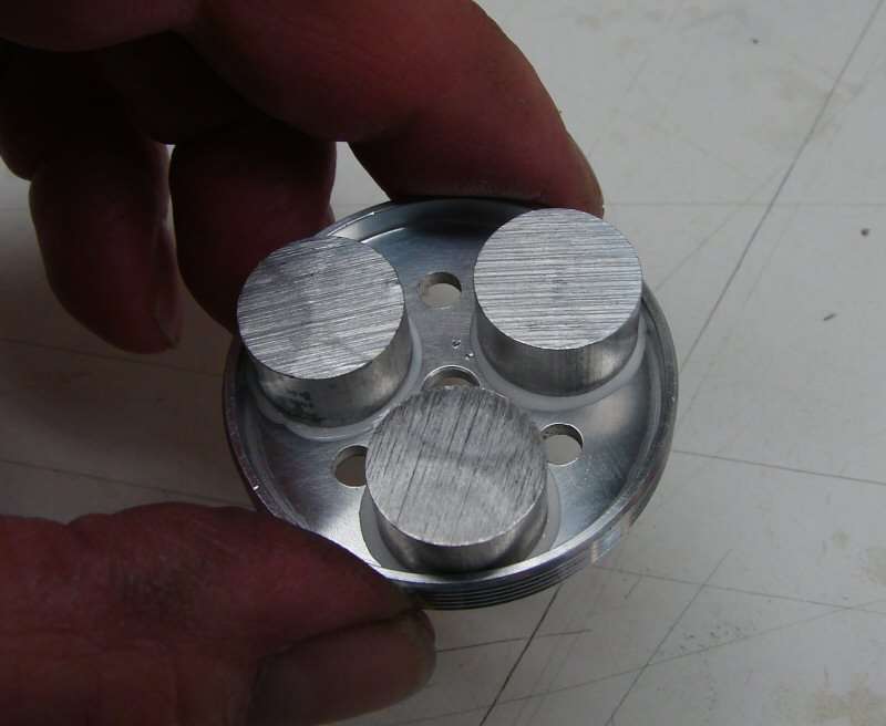
I decided to use three of the heat sinks I had for AA Mags. I used AA and some clamping force to adhere these to the bottom of the LED plate.
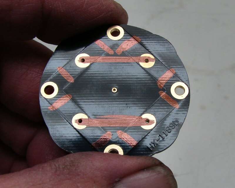
I marked the bottom side of the original spring contact plate and in the next shot I have cut the contact traces where needed and bridged the contacts, so that it works for series use.
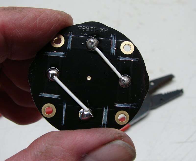
I also have soldered all the contacts for the replacement plate that goes where the driver was. It's all set to go for series use. The bridge on this plate is shown on the back side, as well as the positive and negative wires.
Next is to work on the driver configuration. I have not ordered LEDs yet, so this mod will come to a standstill soon, until I get the LEDs.
----------------------------------------------------------------------------------------------------------
Drivers
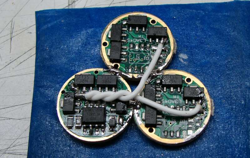
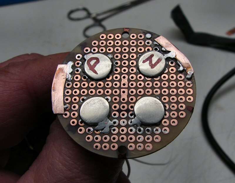
The driver on the lower left is the Master and the other two are slaves. I soldered the outer rings of the three together, so they would have common ground. Then I removed the program chip from the two slaves. I used some of my solid wire to run wires from the master to the slaves. This makes the master control all 24 of the 7135 chips. It's much like soldering extra 7135 chips onto one board. The difference is that now there are 3 sets of 8x7135 chips and each set of 8 will power one LED. This should give 3040mA to each LED if the batteries are able to put out over 9 amps.
I am not going to wire any more till I have the LEDs here. I want to solder wires to the LEDs and position them and then I will solder the leads to the drivers.
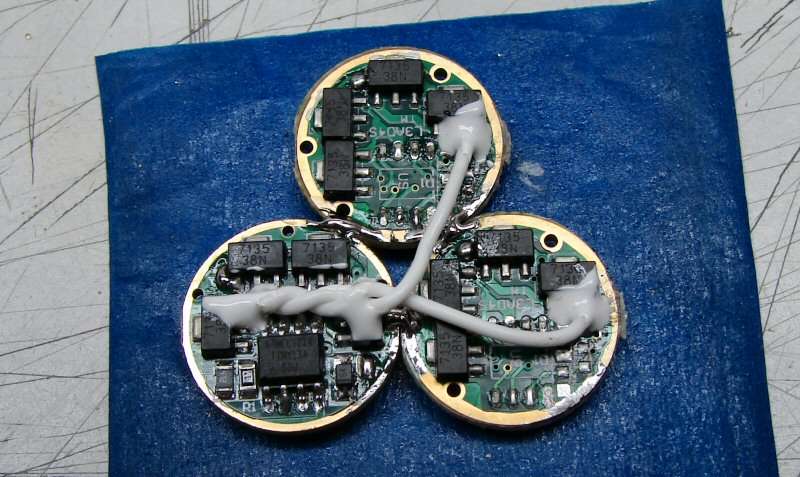
After flexing each connection, to make sure it was good, I used some Arctic Alumina adhesive, to help protect against my own fumble fingers, when finishing the wiring.
---------------------------------------------------------------------------------------------------
That's it till I get LEDs in. NOT
I decided that the difference between XM-L and L2 is not worth the money to buy more leds, when I already have leds. Besides, I need to just use what I got, to get rid of February's debits... Besides, I am not a patient person. So, I used three of the T6 3C leds I already had.
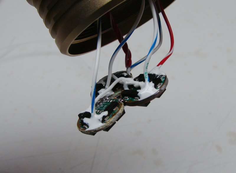
I have the wires from the switch attached as well as the three negative wires from the drivers, to the leds. Once I flexed them all, to make sure the joints were good, I used AA to surround them and help protect them when I try to stuff all this into the head. I still have to wire up the three Positive wires from the leds and one positive to the master driver, to the battery positive. Then the ground from the home made contact plate will be soldered to the drivers and everything will be put in place. I'm getting close and I already tested this thing this morning. It works as advertised. My 3xAA Eneloops weren't particularly happy to be hooked up to 9 amps, but they only had to endure it long enough to check out the UI and verify it worked right.
If everything goes well, I should be done by Wednesday. I have the drivers in the head and I used Fujik to hold them in place. That is drying right now. I don't like Fujik, since it takes forever to set up, but I can't use AA for big jobs, due the the extreme cost of the stuff, so I just have to use Fujik and wait 24 hours.

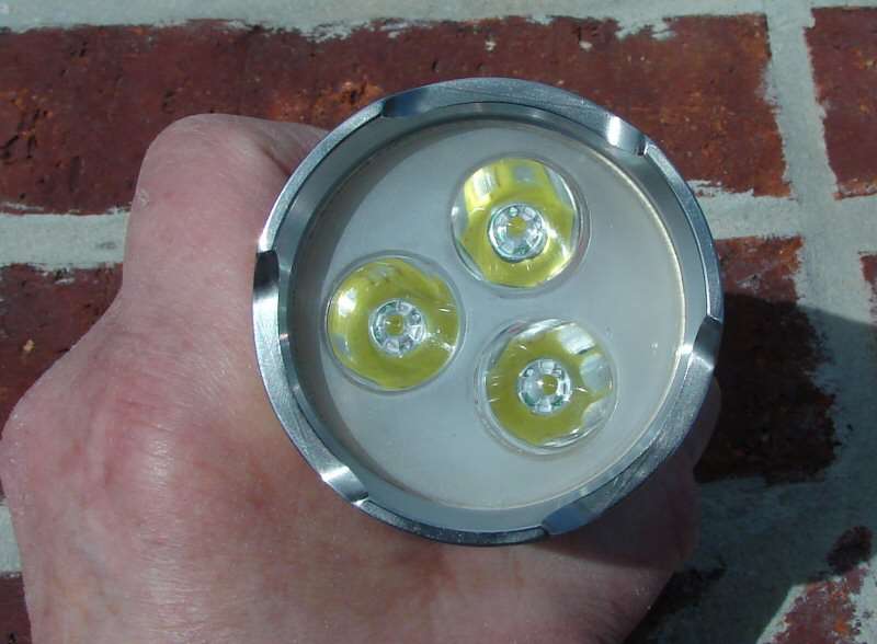
Here's the business end.
--------------------------------------------------------------------------------------------------------------
Not much left to see now. I reach a point where I just want to see it finished and I forget to take any photos. Here's a couple of the last photos.
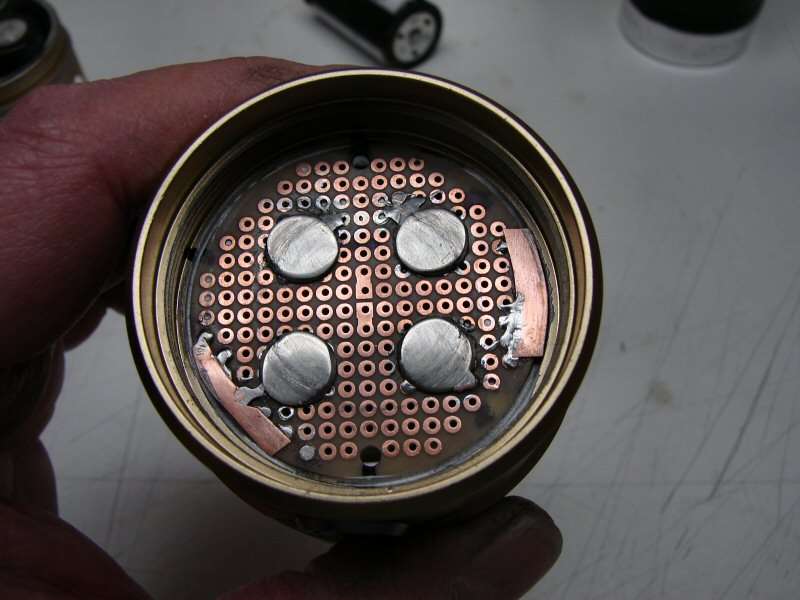
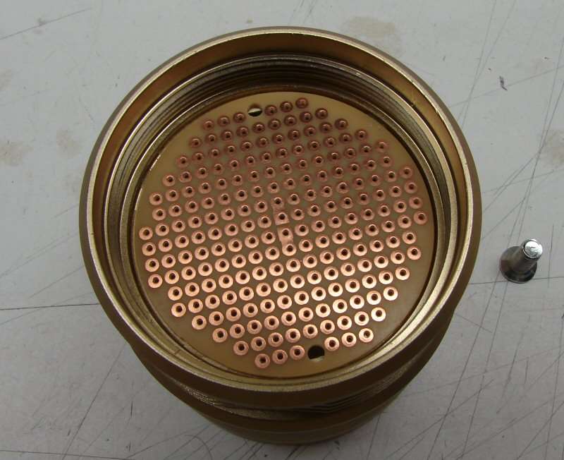
The top contact plate is glued in place
The bottom contact plate and tail cap are in place.
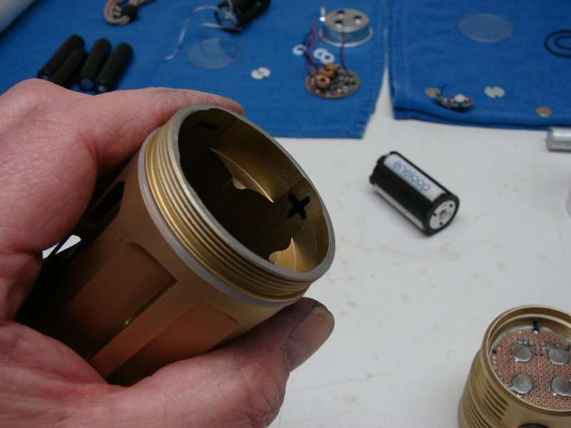
The inside of the body is marked for + or - terminals, for battery installation.

The red line is a marking point to show where the body and head meet, when the body is tightened and the light is working.
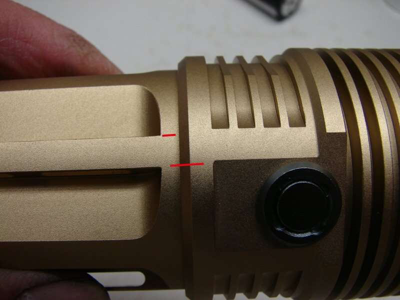
The second photo shows how far the body has to be loosened, in order to break the circuit. It does not take much and it locks out the light.
That's all folks!