I did add 4 to 8, but that board didn’t work and the stacked chips were going to cause issues with the retaining ring. I tried soldering it in…used the solder as a threaded ring to hold the board down and it was pretty snug, but it wouldn’t work.
So a stock board is running my light with the original 8 chips. I might see if I can add 2 to the bottom of the board but first want to see how it’s performing here. The supposed 5A driver I had in it was only pulling 2.38A so 2.87A is a marked improvement.
I was wishful and put the light back together. Click, nada.
I’ve now recessed the ledge that the driver sits on in the HD2010 pill and now the retainer ring sets on top of the chips on the spring side of the board. Can’t add chips there. I think I can add 2 chips on the inside, gonna check into that.
For now, success with the new driver! Nice lo, great Hi, no whiny mosquito sounds….none, zilch, silencio! Happiness!
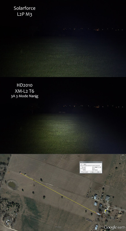
The two military trailers in the beamshot below are pretty dang far back! The second one, where the reflector is shining, is 465 yds! The trees behind the trailers are 550 yds from the hayloft I was in. Not too shabby! The camera settings mimicked what I could see. Canon G1X zoomed to 112mm 0.6 sec f/5.8 at 1250 ISO.
I think the chips could be in the way. Perhaps a longer spring. I've been trying to stay away from adding chips on the contact side, unless the driver is hooked up to a separate larger board from underneath.
To save myself headaches, I now pre-test any driver I worked on. I have an LED that I had swapped out of another light permanently hooked up to alligator tipped leads. I attach the clips to the drivers leads and then touch the pos. and neg. with wires from a battery holder. If the LED comes on...your good to go.
That way you know if your flashlight doesn't work after installation, its something else, like a poor connection somewhere.
I actually did solder a different spring, inverted, onto the board. My 26650 LiNiMnCo cell is more of a flat top so the longer wider spring was used to ensure contact. Only one I had so I had to remove it and put it on the stock board when I went that route.
I actually have a couple of emitters on copper stars sitting right beside me, could use them to check that driver easily enough. Nice suggestion and nice set-up. Thanks.
I cut a set of wires and tried the modified driver. It works! The chip addition is a success! I’m blind!
The XP-G2 on copper star with thermal paste sticking it to a copper bar is very very bright on Hi, Med and Lo modes also work. I will find a use for this driver or figure out how to put it in the HD2010 somehow. Anyone able to make me a copper pill for the HD2010? Anybody?
Edit: Uh, perhaps I should have used 2 AA cells instead of a fully charged 14500. How long does it take for the purple haze to go away? Prince would know….
I have that XP-G2 on copper, and this driver, and I’ve been wanting to modify a MiniMag. Reckon a 4A minimag is too much? Perhaps I could fit this stacked chip driver into my HD2010 and move the 3A stock version into a MiniMag, would 3A be too much? Could the XP-G2 on copper handle 3A safely? Anyone know who could make a solid copper head for the MiniMag AA light? >) >)
My first attempts at stacking went well, but my last couple gave me problems.
I ruined one driver (don’t know what I did) and the last one, I couldn’t span the gap of the last set of legs with the solder, no matter how hard I tried.
My solution: I stripped a piece of small gauge wire I had removed from a driver, tinned it, held it vertically against the two legs, touched the iron to it until it attached itself , and snipped off the excess at the top. It worked great.
Hmm, that makes me think…what if you stripped a wire a little longer than that bridge between the legs, tin it, then hold it to the legs and make that touch to connect the legs. Snip off the remaining wire right above the upper leg. Might be the easiest way yet as you’ve got the wire to hold it in place by with the tinned portion ready to grab the legs as soon as the iron touches. Voila!
Gonna have to try that next time….if I can remember!
I find it more difficult than just using solder. The wire has to be really thin. I wonder if solder alloy is a factor… 60/40 vs 63/37. I use the former. Maybe I will pick up some of the latter and try it.
I don’t see why the wire would have to be thin. I just soldered 2 together with 20ga silicone covered wire. Like attaching a pillar in front of the legs, lol. Of course, in this application I’m leaving the wire some 3” long and using it for battery contact and emitter contact.
Hey Ouchyfoot, do you attach the top chip before soldering the legs or do you use the ground solder to hold it in place?
I don’t have anything to attach it with first, or the patience to wait for Fujik (if I had some) to dry. So I just hold it in place and solder the wide ground on the back side first then do the other 2.
I just fasten it on top of the bottom chip with a dab of super glue from the dollar store.
On my next attemp, I might pre attach small wires to the legs of the bottom chip, glue down the top chip, bend the wires up, and attach them to the top legs. I’m also finding it to be easier, and neater to link the thermal pads with a bit of narrow copper braid.
Isn’t the internal bond wire encapsulated inside the chip? I mean that inside the black part, is it just a cover, or is it like potted? If it’s potted, then it seems like that internal wire bond should be pretty secure, so I’m kind of surprised that bending the external part of the leg would break or weaken the internal bond. I haven’t worked with 7315s, but I’ve done that (bend legs/pins) many times, especially while prototyping.
I tried bending the legs down. It sounds easy, but its not, unless you are experienced, and have certain dedicated tools you use. I just ended up breaking the legs off, ruining the chip.
I am new to light modding. Added several 7135s to a few drivers. Bending the legs with needle nose pliers has worked fine for me. Def makes soldering easier.