Just wanted to share my findings with the driver found in this drop-in.
This is not a very in depth review. It does lack some important measurements, but I believe it gives a fairly good picture of the driver.
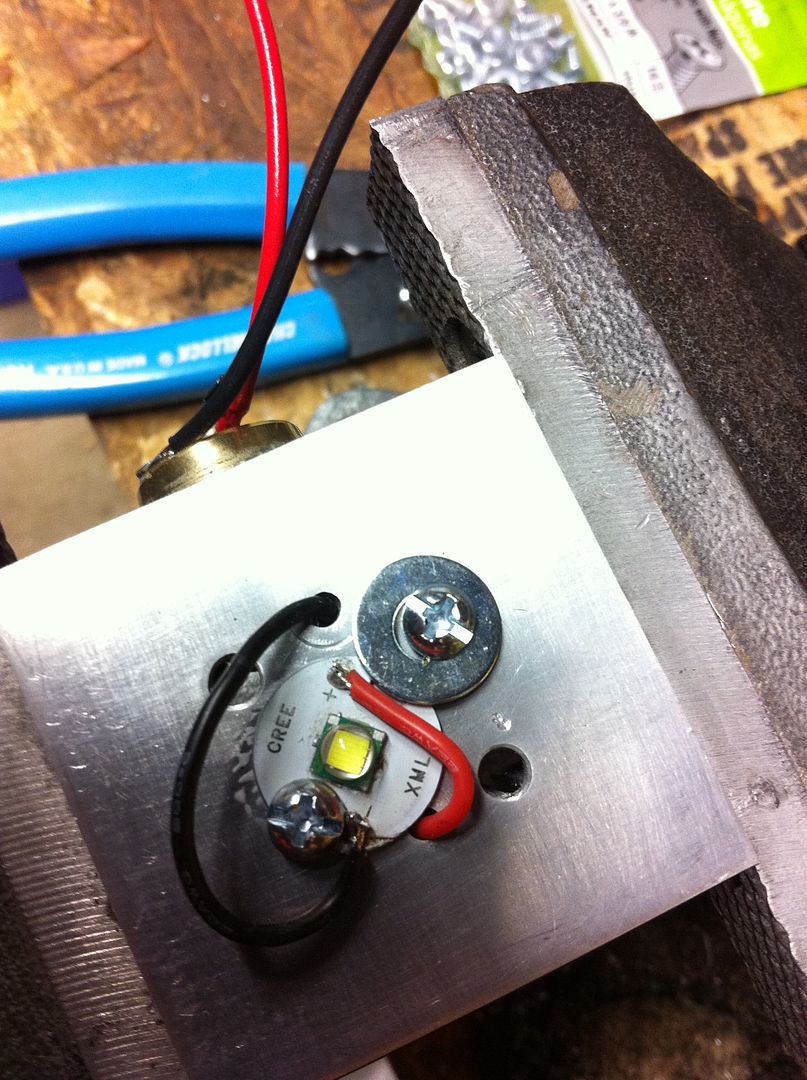
Out of the P60
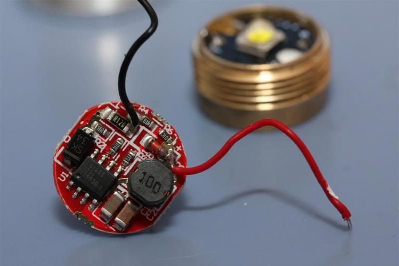
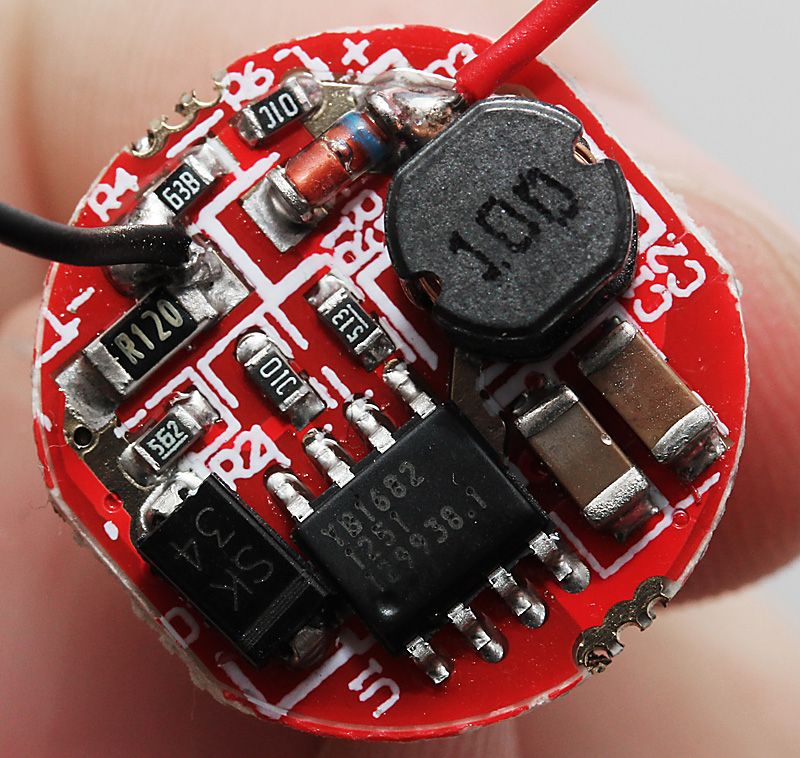
Close up
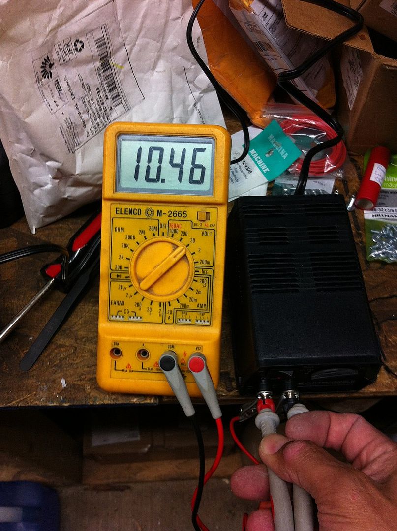
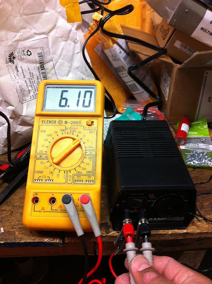
Here are some tail cap readings I did not long after I got it.
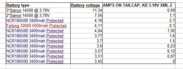
(battery voltage is not measured under load. These measurements were done with the P60, so in combination with XM-L2)
As you can see, its quite useless below 3,7V. Seems to be a 3,6-18V driver too me. Once again, KD messes up facts.
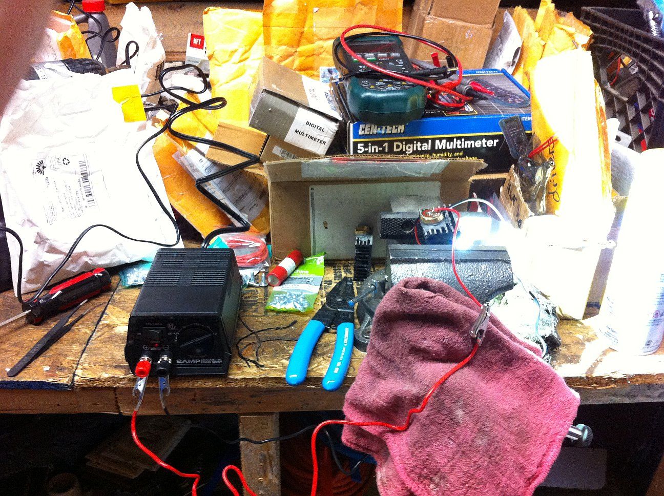
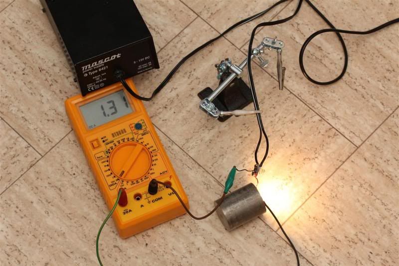
I measured amps to the emitter yesterday. Started out with a battery pack. Barely used eneloops that was charged around 2 weeks ago.
Emitter: XPG2 on copper.
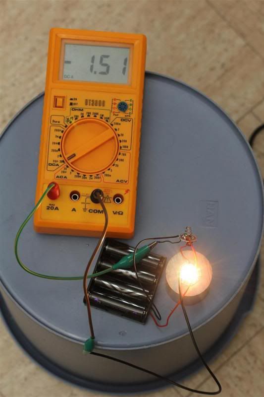
1,5A to emitter
Im pretty sure I tested it with 3 batteries too. And saw about 1,5A (but not 100% certain when writing this)
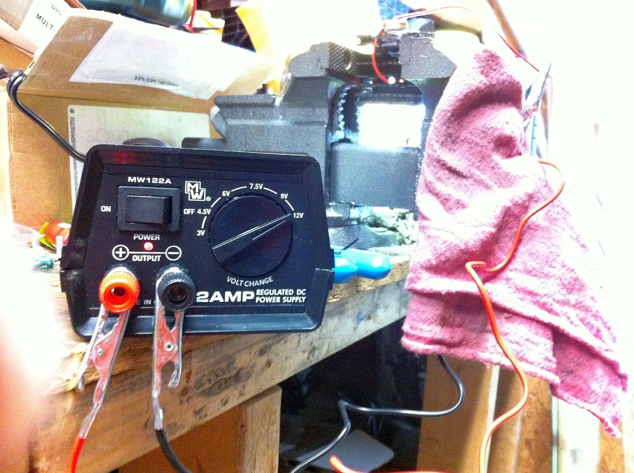
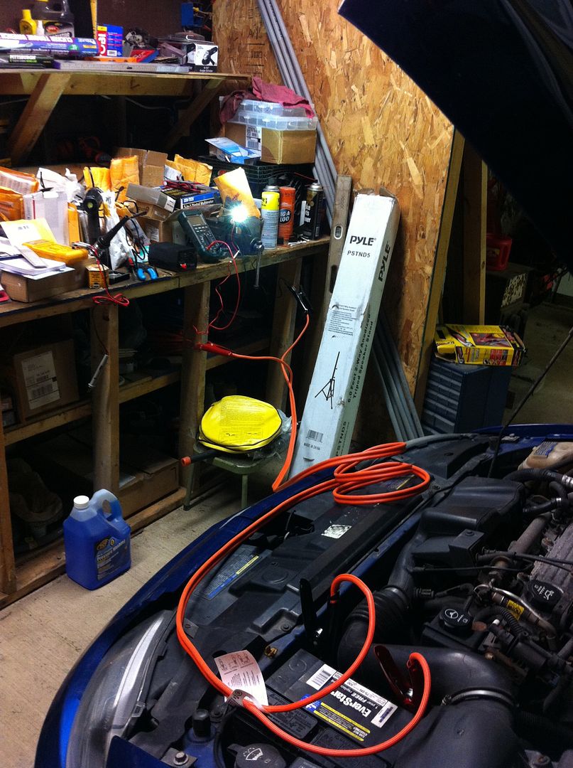
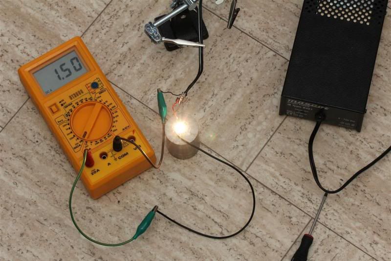
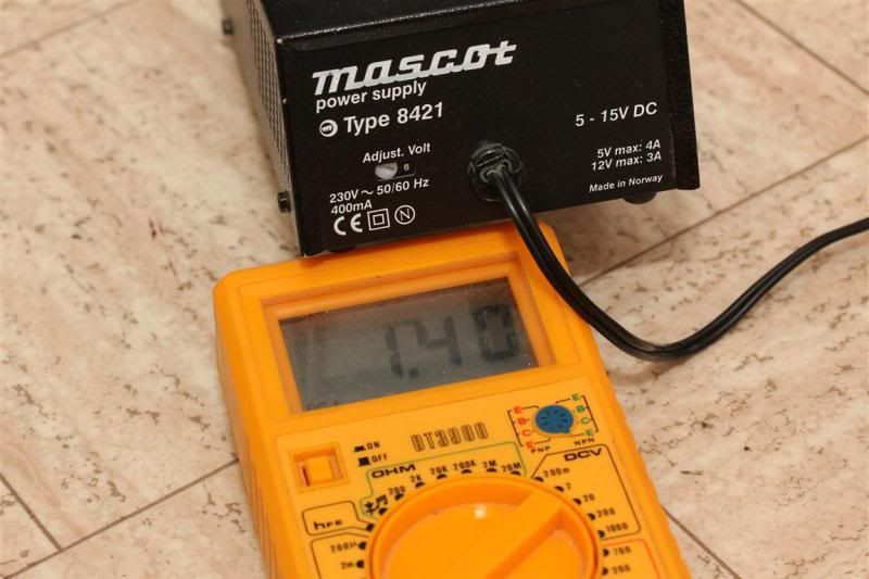
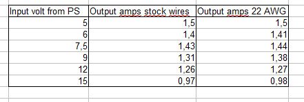
Changed to powersupply (5-15V)
5V
6V
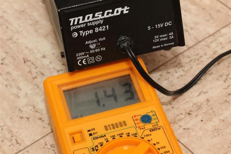
7,5V
9V
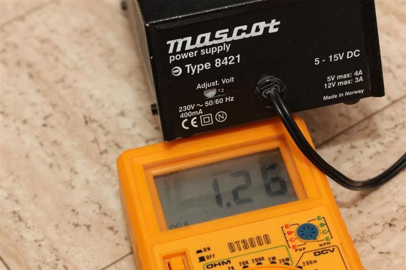
12V
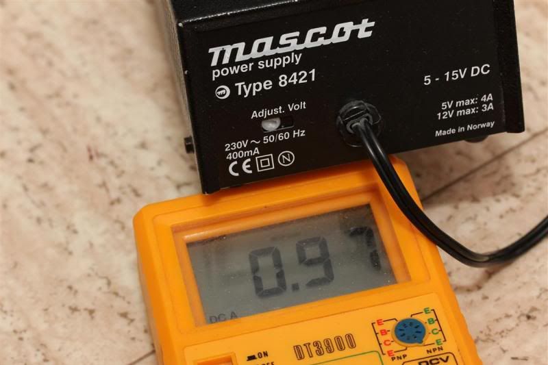
15V
That gives me these numbers in the middle column below. I did the test once more with 22 AWG wires. Still same results. The small differences are most likely me not setting the power supply on precicely the same setting. (as pictures show, its only a scew, not a digital display with output value)
People are free to draw their own conclusions. Many people here have way more knowledge than me.
My thoughts:
Based on the numbers I would say its a mediocre if you are only using 1-lion. 2,1A input. About 1,5A to the emitter. Very roughly, efficiency seems at best to be up towards 70%, but generally lower. Problem is, when voltage sags below 3,7V its useless. So if using a battery like the NCR18650B (3400 mah) you will not get full advantage of all the capacity. By looking at tailcap readings, the numbers goes down when battery goes below 4,1A. Basically right away. I never measured amps to the emitter with a lower voltage single li-ion, but I suspect that output goes slightly downwards too (or maybe efficiency goes up). Whatever it does I would either way say its either best suited for 2 li-ions or 4-6 AA batteries.
You can push it beyond 9V, but output goes down a lot. Its quite noticeable when changing the voltage on the power supply from 7,5-15V.
My conclusion: All in all, very flexible simple little driver. Its cheap too. In order to get highest output and probably best efficiency, input voltage in the 4,0-8,4 V is recommended. 4xAA batteries looks to be a very nice combo for it. Its also very suitable for 4-6AA batteries or 2x li-ions.
Thanks for reading
Feel free to come with input on how to interpret the values I have measured.
Question to readers: Does anyone know of a better small 3-18V driver that are better with similar or higher output?

 I have yet to see one with anything that is sufficient. I get tired of doing it but it just makes a better light in my opinion. I like the silicone / teflon wire better anyway.