i like the way you think!
If I remember correctly, about a 95-96mm would be about perfect. The stock one and the SR90 one are both about 93mm. They work ok, but have a fair amount of play.
The 59 mm UCL/p fits both HD2010's and Small sun T08's (got one on each) - I like them, would be better maybe with glass, but flashlightlens doesn't make the big UCL's.
beamshots?
rdrfrtonty can have the pleasure - I'm backed up here...
this is making me regret selling my btu shocker …. but at least it went to dale who did a similar mod haha
Yep, I’ll make sure to do some beamshots when I get it back. Brother and I just got back scoping out new photo target areas. Found a good spot with good potential for 500-600m shots. A long pipeline right-away cut through a national forest. The path is roughly 25-30m wide I think. Want to do the BTU, SR90 (w/ SBT70), TN31mb, TN31 (xml2 dedomed), TN31 XML2 (on copper), and TK75. Will likely throw in a couple more moderate throwers like 7G5, M3C4, & SR51 for comparisons sakes to the serious throwers. We want to do full distance shots of the 500-600m, and then get perhaps 25-50m from the target to show much better how much light actually makes it there. That way we won’t have to worry about zoom screwing up the long distances. Not sure how much light those last three will get to a target that far, perhaps none, but maybe .1L or so.
So is the plan anyway.
Very nice! Looking forward to hearing how it stacks up to your other lights now. 8)
Thanks for the link… one on order ![]()
the cool thing about Fenix TK75 is … it can add several battery tube extensions ( Fenix engineers tested up to 9), but it ain’t cheap at $40 a pop, could have bought another light ![]()
maybe someone with lathe can create battery tube extension for BTU? ![]()

Ordered one as well, thanks.
OK, there is definitely something wrong with my BTU. I did the exact same mod and I get much lower throw numbers, even lumens. I think the reflector is bad.
Can someone take a closeup picture of the reflector surface? Mine looks weird. I’ll add a pic in a bit. I want to get to the bottom of this.
For reference, mine is driving 3 XM-L2 U2 emitters on 20mm SinkPads. The driver died, so it’s DD now; at 5.5A! The kicker? I get 115kcd (measured lux at 12 ft and calculated). That’s almost the stock throw, not quite. Makes no sense to me. I’ve tested with the lens out too; only adds 12kcd or so.
Lumens are around 3050 after 30 seconds. Add ~200 with no lens. Still well short of the OP mod, and I’m at 5A+.
:~
Edit: Close-up of reflector surface:
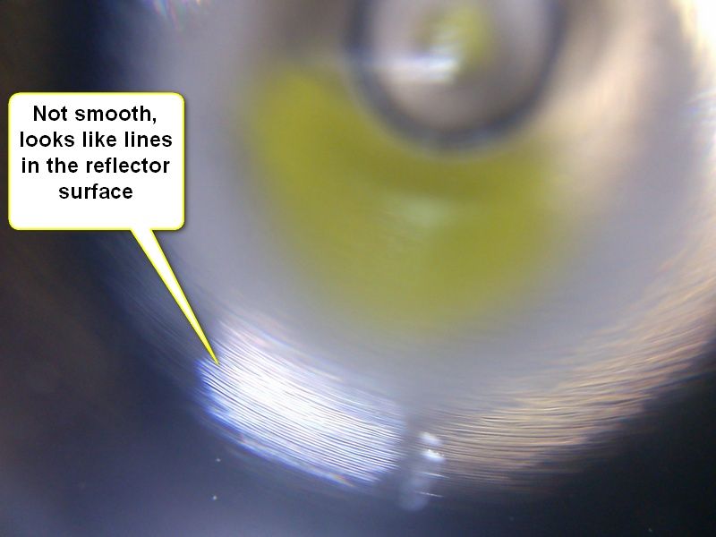
Maybe its not in the reflector but the lux meter differences, or calibration between the two. Are all 3 reflective surfaces scuffed like that, and does that swirl remain uniform throughout the entire surface? Ive had a few reflectors where I could see that someone had cleaned them with a rag and scuffed them, but the swirls were not patterned throughout the entire reflector surface.
relic - oh boy, the Shocker is in transit now so don't have it, but those lines don't look familiar from what I recall. Hhhmmm, I did before/after measurements of the Shocker also, so emitter upgrade seemed to be true. I also did my throw measurement at 4.3 meters, about 13 ft. The good thing is the mod'ed light is going to rdrfronty, so he will do full measurements and more reliable outdoor distance measurements on the throw so we'll get confirmation, good or bad.
Man, the driver died?? Did you have the original or the Dry driver? That really sucks, sorry to hear these issues. I'm sure rdrfronty could provide some input, but he won't get it til the weekend. Had a small "shipment" of mod'ed lights going his way... Whewwww.
Yes - that option would be awesome for a Shocker, but man, that TK75 is so well engineered...
Possibly accounts for some of it, but our HD2010 XM-L2 SinkPad numbers matched up quite well. It does not look cleaned. It looks like machining lines under the reflective coating, tbh. The front flat surface is mirror smooth, the reflector surface looks like it was taken right from the machine shop to the coating lab. No alu polishing in between.
My driver died because of me. I think I reversed the power. It was the standard driver. I have ordered two DRY drivers, originally for another project. No word from Ric on when they will ship yet. I will put one of those in the BTU. Once I can compare BTU reflectors, I’ll know if I should ask for a new reflector. Compared to an HD2010, C8, or just about any SMO reflector, my BTU has a poorly surfaced reflector.
Hey Tom do you think you could do a brief guide or instruction list on how you did this mod? Also I was thinking of putting XML2’s in my BTU, can I do it with the stock heat sink? I have some Arctic MX4 paste I could use with the stock heat sink.
Thanks!!
The BTU has a decently smooth reflector. It’s not as smooth as my brothers TK75, but not bad at all.
As for your numbers - yeah something’s up. I will get my light back from Tom tomorrow and I will retest it ASAp. Tom and I have tested the sveral lights on both of our meters and lightboxs, and they usually read pretty close. Your numbers, especially the throw is pretty bad. Worse than stock.
So I guess you can get your new drivers in and see what they do. If the results are still poor, I guess you might need to contact Ric and see if you can get another reflector.
Oh boy, where can I start... This is/was a scary mod - it's difficult taking on a mod job on a light you've never done before, and it's not yours! It's someone else's pride and joy, and their investment, oh - and it's the biggest, most expensive light you've ever worked on, and also, your first multi-emitter upgrade you ever did -- no problem  . So what do you do?
- the plan - only doing an emitter upgrade, that's it. Well, upgrade the wires to something heavier, better, and XM-L2 U2's on SinkPAD's. Word is the thicker, bigger stars should fit fine. Take pics along the way - the pics, as it turns out, will be your reference (but I never take enough pics! Always forget).
- Tear It Apart! Well, the driver assembly unscrews - bad thing - you'll have twisted wires (remember this later). So, it comes apart easy, 1 phillips heard screw in there to hold down that massive reflector, take the screw out, unscrew the bezel (real nice threading by the way on the bezel), pull out the massive, heavy reflector (did I mention the reflector is heavy? Again, remember this for later!!), unscrew the collar that surrounds the reflector to get better access to the LED's
- Desolder the emitter wires - funny, why are the main wires from the driver thinner than the short wires between emitters? (think I found out why - twisting heavy wires doesn't work well)
- pop off the epoxied 16mm stars - left some scratches, but surface will be sanded/polished anyway later, though should have been more careful
- Now sand/polish the pill top to 2500 grit, nice and smooth
- re-flow the XM-L2 U2's onto to the SinkPAD - old frying pan method, works great again, test those reflows - looks good!
- sand/polish the SinkPAD's to 2500 grit
- Plan on mounting the emitters - I believe AS5 is the best way to go, not epoxy. So, after they are wired, you can freely position/align them. And that super heavy weight of the reflector that's screwed down with one center screw will firmly hold them, maximizing contact for thermal xfer. Will there be twisting pressure, putting the wires at risk? HHmm, maybe? So use epoxy on the outer edges of the stars to help locking them in to position.
- Position the stars by using the reflector, and mark the positions - perm. marker on the actual pill top. This doesn't have to be precise because these will be on AS5 later, and will be moveable to a certain extent.
- All the above was the easy part, now comes the wiring... Plan originally was teflon coated 20 gauge, so soldered to the driver (oh - detailed pics of the driver showed me where to solder!!). I was thinking I could avoid wire twists by using the driver wired, screw the driver in, the after, solder the wires to the stars -- No, stupid, that won't work, because the driver has to be out in order to get to the screw that locks down the reflector! Ok - twist the wire then - No! Teflon coated, silver tinned wire doesn't twist well, pretty much not at all -this won't work. So, delay the job while ordering silicone 20 gauge and 22 gauge wire (use 22 gauge if 20 gauge doesn't work out).
- 20 gauge silicone is in - de-solder the teflon wire, solder in the silicone wire - use kapton tape to wrap the red and black wires close to the driver as a strain relief because of the twisting pressure on the actual solder connections.
- So all set, leave enough slack so the driver can be pulled out enough to get to the screw, set the stars in the AS5 in the marked positions, cut/solder wires intereconnecting the stars (use your pics as reference again!), then solder the 2 main wires. Ok - this soldering is not so easy - you are working vertically down, into the pill top, and for some reason, it wasn't easy to get good solder connections - maybe it's this new wire, not sure.
- Now all soldered, but you need to protect the + and - solder points because the bottom of the reflector is flat and will ground the wire connections. Now I chose to use kapton tape here. Also I re-used the XML alignment rings, but they don't elevate the reflector much off the star, so the kapton tape does it's thing. Unfortunately I don't have any of those XML isolation glue-backed rings that are built for 20mm stars, only for 16 mm stars. Do they even make them?
- So now you are set to screw down the reflector, then do several CCW twists of the driver in order to CW screw it in, so maybe twists aren't too bad.
- All done? no - assemble the bezel and collar around the reflector -- ooops, something is wrong! I secured the reflector, but it's impossible to get the collar down around it! Crap - the collar has to go on first before the reflector, duh. So, take it all apart, now screw on the collar, and now drop in the heavy reflector -- wait, this thing is damn heavy and I got nothing to hold on to - I gotta let this 5 lb hunk of aluminum drop like a 1/4" onto the emitters? Well, let it drop carefully, and precisely. Did I mention this now $150 plus light is not mine? Well if I could put my greasy fingers into the reflectors, no problem. No - not an option, so, let her drop!! I did, and it seemd to work - positioned it, screwed it down, CCW'ed the driver before screwing it in. Now, easily screwed on the bezel with the glass (AR in this case).
- Fired it up - wholla, let there be light, and a whole lotta light!
If you suspect the 20mm SinkPAD thickness may be an issue, I dont' see it - the reflector may be raised somewhat, but there are so many threads on that bezel, and the way it seats, I don't see anything noticeable. I really like all the threaded connections on the Shocker - seems to be quality and lots of threads.
HHmm, did I mention the reflector is slighty over-weight? I really can't understand why - don't see how it could be used for heat sinking..
PS: I'm sure I left out some details (and mistakes) either forgetting or too embarassed to admit  .
.