yup, ima4wheeler and I are both using 2S cells. I haven’t tried 3S.
I just noticed another difference. Mine has some type of epoxy between the to boards. It covers some of the components too. I would probably destroy the driver trying to separate the boards.
Interesting. When did you buy it?
The one I have in a light looks like the one pictured, and I bought that over a year ago. I got my other two from another member a couple months ago, and I think he bought them before I bought my first one.
2/21/2013
Oh dear, I’m probably too late to contact manafont about it now too.
I had thought about using it in the DRY but even after seperating the boards and wiring connections so they aren’t at a right angle anymore it still didn’t fit.
Ok. They must have changed the driver design, but not updated the website pictures or they sent me something different. 3 sensor resistor pads, R2, R5, R7 with R200, R250, and R100, respectively. Here is a picture:
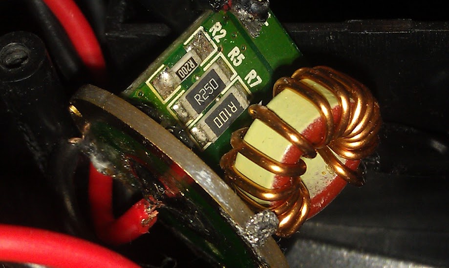
Huh? .200 .250 .250 ohms all together, how is .056 calculated?
definitely a change, and not just position of r2, because my r2 says 103 on it
Is the R2 you’re refering to on the same side of the same board? I ask because I doubt the driver boards are coordinated that well with each other. I wouldn’t be surprised if you saw the same addresses (i.e. R2) on both sides of the same board.
If you mean, is there another location labelled R2, then no.
you can see R2 in the first pic I posted, but can’t quite read the value. I used a 7g5v2 collimator lens to read it lol
when checking I noticed that both of mine have some markings you can’t make out in the photos
TR-0159B
and
2011-06-18
Ah. Good idea. Mine say:
TR-0159D
2012-01
My board has the three same resistors in the same places as your ImA4Wheelr except they are all the same physical size on mine. Also there is a R2 on the bottom contact board that has 103 on it. I just got in .12 ohm resistors. Where should I add them to bump power?
Thanks for starting this dthrckt
you can solder them directly on top of the existing resistors or in place of them, depending on what level of resistance you are shooting for.
I second that. Thank you for starting this thread dthrckt.
Tried to get a little more info off the driver this morning.
- The adhesive residue is fairly easy to remove with a pick. It is flexible, peels and crumbles. This is very good news from a modding stand point.
- The round board is labeled, “TR-0159C2”.
- The MCU has 10 legs and appears to have this code on it, “TR35”. Difficult to read due to adhesive residue. I’ll take another look at it tonight. It would be nice to identify this chip to see if we can program it.
I tried last night and again this morning. I can’t make out the labeling on the mcu. I would be nice to be able to reprogram this driver since it is low cost and easy to modify it’s power output.
I had this pic to refer to, which shows .100, .250, and I assumed a safe .250 for the underneath mystery resistor:

The more recent picture from 4wheeler shows .100, .200, .250 on a slightly different driver.
Can you show me where you got your values from? :~
I just received this driver and there is no resistor on R5, just 2 blank pads. Should I be concerned?
What does the the label say on the one resister you do have?
EDIT: Does it appear that there is more than one resistor stacked?
next to r5 is r7, it has a single R050
That is pretty much in line with the cummulative resistance of the 3 resisters (R250,R200,R100) that are normally in place. Should get you around to 4.5 amps of current.