Ah, but if we could only pick one we wouldn’t be here on the forum! ![]()
I noticed that the box for the S1100 has little notification boxes stating CreeLED waterproof standards etc, and on the S1100 it states 700m throw, in this space on the S2200 box it states 2200 lumens instead. No mention anywhere from Solarforce what it should throw. So they don’t intend it to be a thrower, just an impresser! ![]()
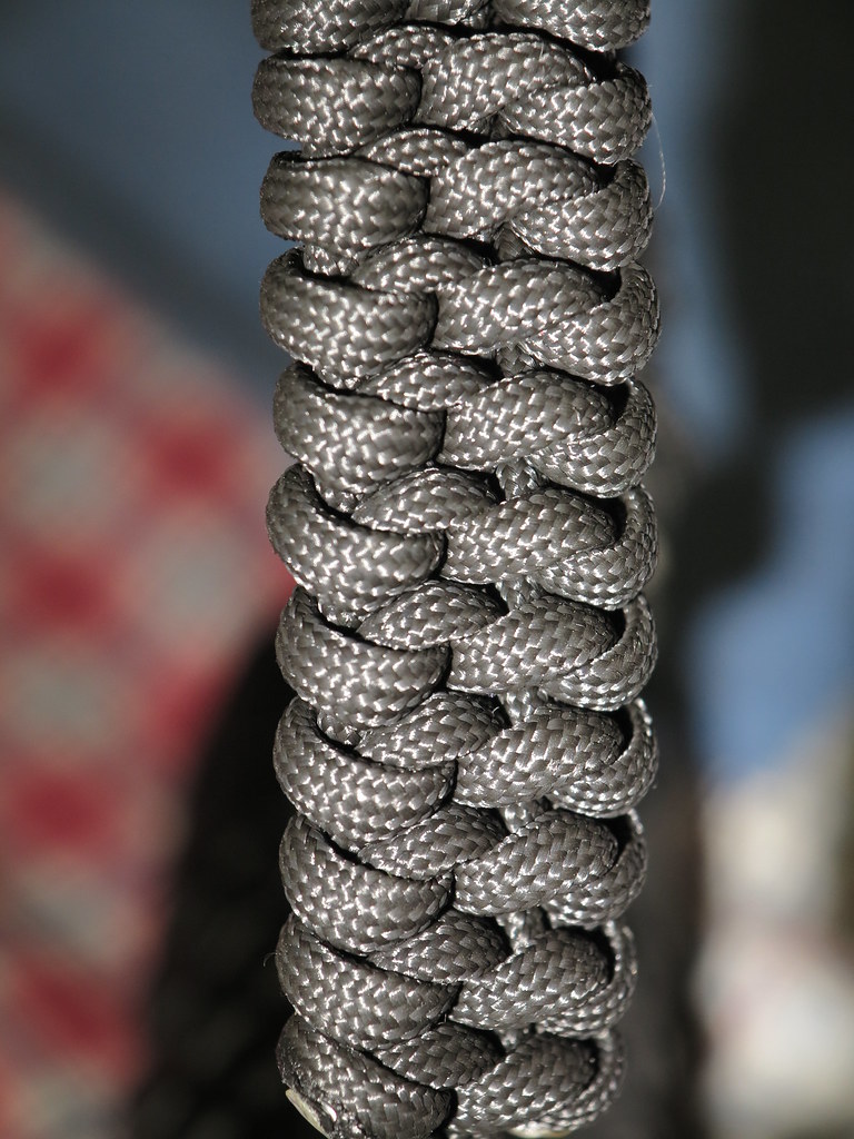
Not wanting to drop this beast, I learned how to tie paracord to make a tether. I meant for it to loop around my wrist and attach, but as it was my first paracord knot…that didn’t work. So I learned a new knot and made an attachment point ahead of the mode selector switch to make a handle out of the main knot, called Mated Snake Knot (the attachment is a basketweave)
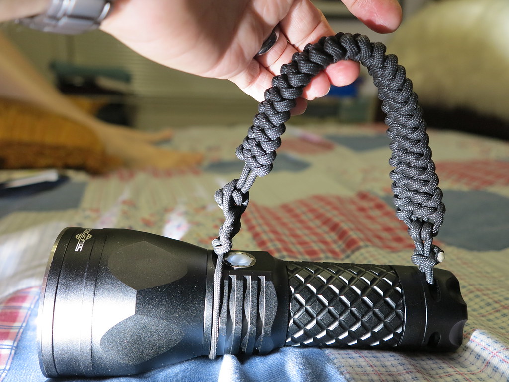
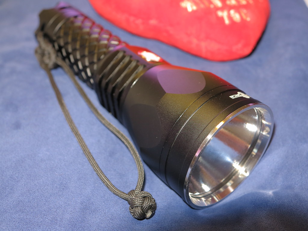
But this was too big and bulky, so I cut it off and made a simpler tether, utilizing the basket weave at the tail and then a round ball to close off the loop. So now it slips over my wrist and doesn’t get in the way of on/off moves with my thumb or mode selections either, but it is secured to my wrist if I drop it or need to let go while remaining easily removable.
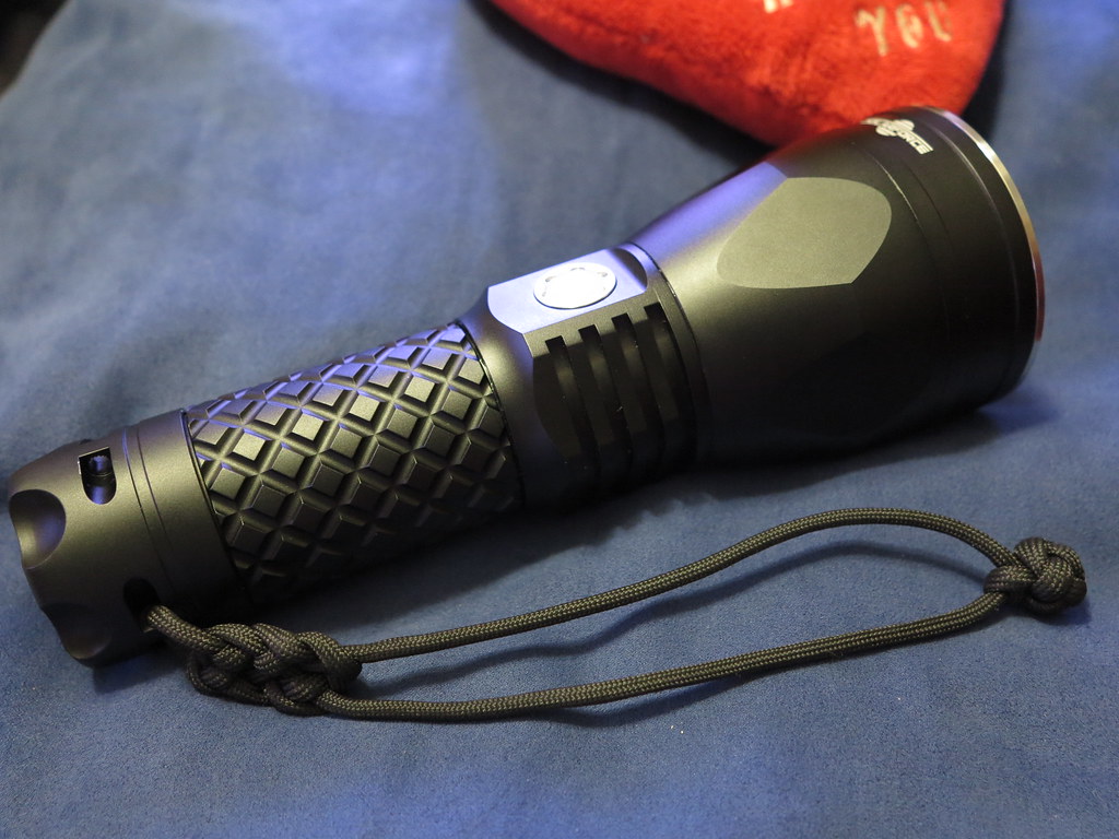
I like how the basket weave compliments the knurling on the battery tube.
Not bad for my first day of knot tying, says I. ![]()
Says I too, nice work.
Mine's getting shipped tomorrow! YAY! (hopefully)
Just hope it doesn't distract me too much from handing in my thesis. 
Wire up the S2200 to a shoulder harness, turn it on hi over your head, turn in your thesis glowing like a gifted child. ![]()
Edit: Mark this post, 238, come back and check it…comfychair said it first and I’ll back him 100%, this light has the most awesome tint and produces so much useable light you will love it! Refer to this one, 238, let us know it ain’t so! ![]()
Edit II: Tail stand it in a room, any size room, and stand amazed at the gorgeous light filling the room. Overpowering the overheads most likely and almost certainly with better color. Do it. Watch.
No, others said it long before I got here (Match, in his bench tests, here, for example).
Maybe this is just the way high(-ish) CRI parts/tight binned/whatever are, but all the other 'neutral' or warm tints I've seen, I can't help but constantly think they are trying too hard to be a certain color. Shine them at something, and you're constantly aware that there is a colored light being shone onto the scene. But this one, whatever 'color' it is, it's transparent. You're never aware of what the light's color is, unless you compare it to other LEDs in the same setting. (I recommend not doing that, comparing this one's color to your other lights, unless you want to think less of the others)
Thanks. Makes sense.
Think I know the answer, but can anyone compare the S2200 to a NW BTU Shocker?
Me too, can’t wait to see some beamshots and personal commentaries. Those are sweet lights and w the BTU at a new price point (and presumably the L2 U2 version not too far behind), they both have their strengths and weaknesses…not to forget the Fenix either.
With neither the SF or the Fenix being readily moddable, that already puts the ribbons around the BTU for many at BLF.
So you like this light, a bunch! Nice.
Waiting to see comments about this vs the Crelant, the BTU, the Fenix… I’ll be able to buy one. Shame on my budget, sounds like I need 2 at least…
The head is nice, the switch area is nice with it’s threaded mount….wonder if a plug could be made to cap it off at the switch and wire it in to the 12V car electrical system, mount 2 of the head/switch units on a bull bar for “driving lights” WOW! ![]()
Not sure that is entirely accurate… comfychair modded his S1100, which is essentially the S2200s sister. But I understand the BTU is probably more “modification friendly” in general.
Crappy lights have more room for improvement, and are generally cheaper (at least initially). S1100/2200 needs what, exactly? Already has a very very nice double AR lens. Driver's current sense resistors are easily accessible, emitters are easily swapped. Upgrade the wiring from contact plate to driver and from driver to LED, and what else needs fixin'?
I just pulled 2 of the 3 screws off the driver cover easily. The 3rd was tight and I wasn’t quite willing to go there. But no red locktite on the first 2.
Comfy? Do you think it’d be doable to get that dielectric layer out from under the emitter if the cover plate isn’t done with locktite? I don’t like that. Want it gone.
With the 2 other screws out, gently pry the cover plate in both directions, if that last screw isn't loctited that will loosen it up (it's only located by the screws, there's no counterbore fitment of any of those parts, so it will move around with just one screw in). If you can get the plate to rotate and it doesn't loosen the screw afterwards, it's likely got the loctite curse on it.
You can lift the MCPCB up away from the base (too much heat transfer with it still touching, makes soldering difficult) and unsolder the wires without removing the cover plate.
edit: I don't know what kind of board they use with the MTG2 version, curious to see if it's the same style as the XML.
If I decided to attack this, is there a way to make the driver step up to higher amperage? Would like to see it realizing a little closer to it’s full potential…not looking for 9A but…ok 9A would be fantastic! LOL (Serial #9, order number compressed to 9 according to numerology, so why not 9 amp?)
But seriously 5A would be great. Think that would be something I could do while I was in there? Or is that getting considerably more complicated?
You need one of these...

I don't know if anybody's worked out what does what on the sense resistors yet, but decreasing the total resistance will increase the current. There are 4 resistors all in parallel, R240 & R220. Adding more resistors in parallel decreases the total resistance. There are many web page calculators to figure out what any combo of a given array of resistors will be, but the rule is, resistors in parallel will always be less total resistance than the lowest value resistor...
I don't know what those R220/R240s measure, probably 2.2 & 2.4 ohms. Adding another 2.4 ohms stacked on top of any of the originals is probably where I'd start, assuming that guess at the originals' values are correct (I would remove at least one of each, and measure before picking what value to add).

Comfy,
Do you know the voltage drop across the resistors? Since they appear to be in parallel it would the same across all four (so no need to measure all four other than to confirm their parallel topology). Knowing that voltage drop (current output to the emitter is helpful too) will let us determine what values to add to set emitter current at 5A.
No not ready to dive into that right now, got too many other things in a million pieces already... S)
Anyone that ordered after solarforceflashlight-sales went on hiatus, got a shipping confirmation/tracking number yet?