FLASKLITE - Nickel's Handbuild Copper Zoomie

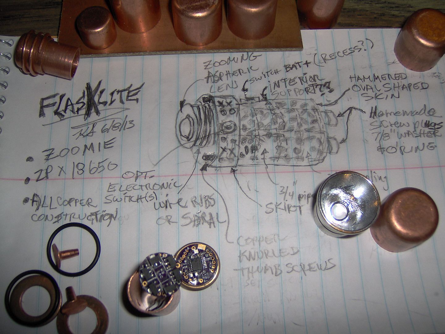
My idea is to create an antique looking copper zoomie. Going to throw out a sketch I made, and hopefully I can execute. Given time, there could be some surprises down the pike.

P60 Mods for zoom function. Double o-rings!!!

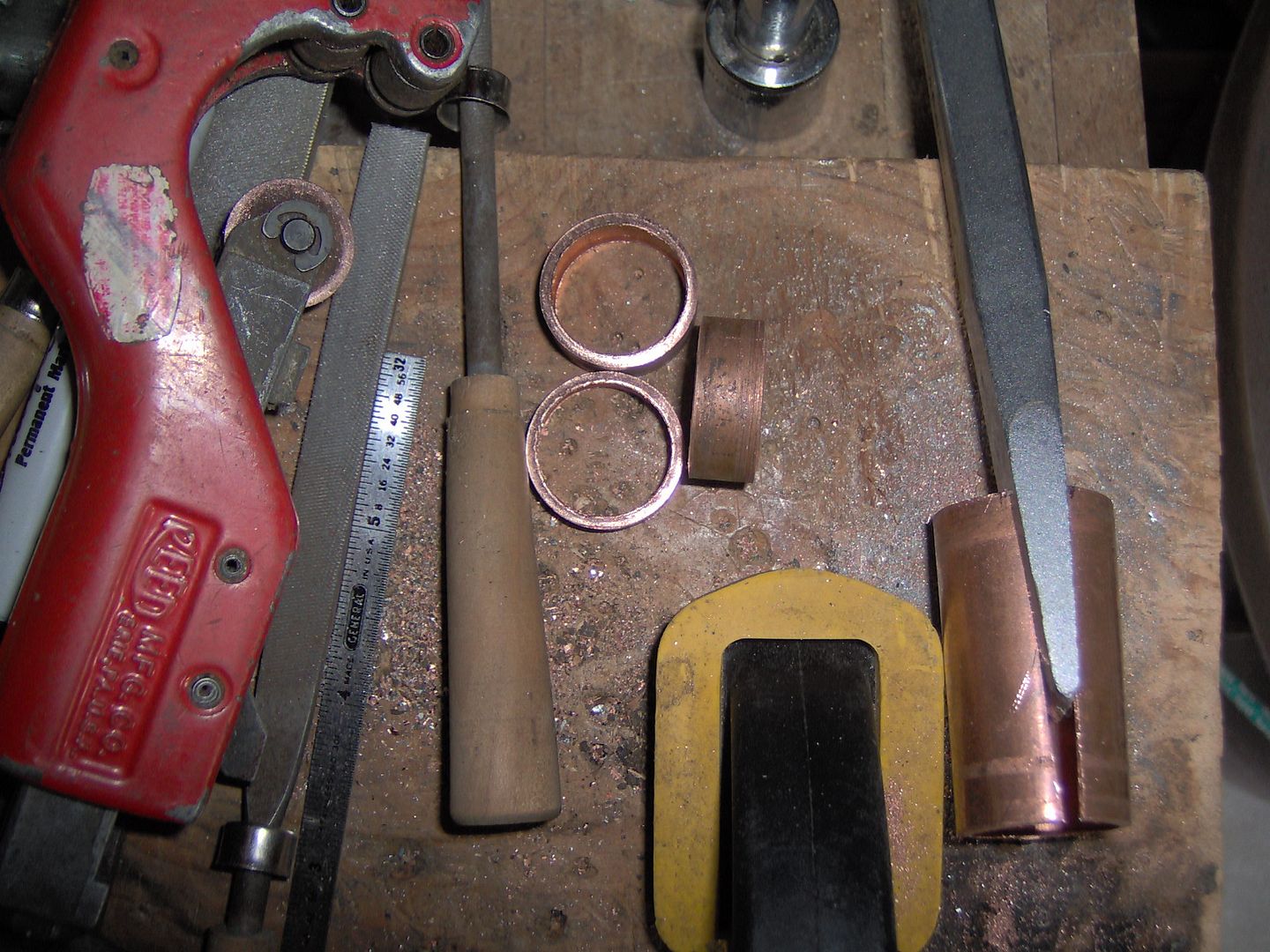
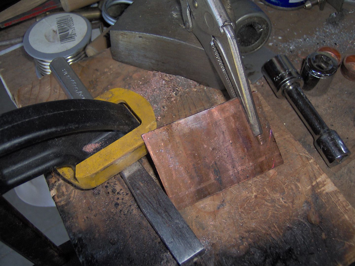
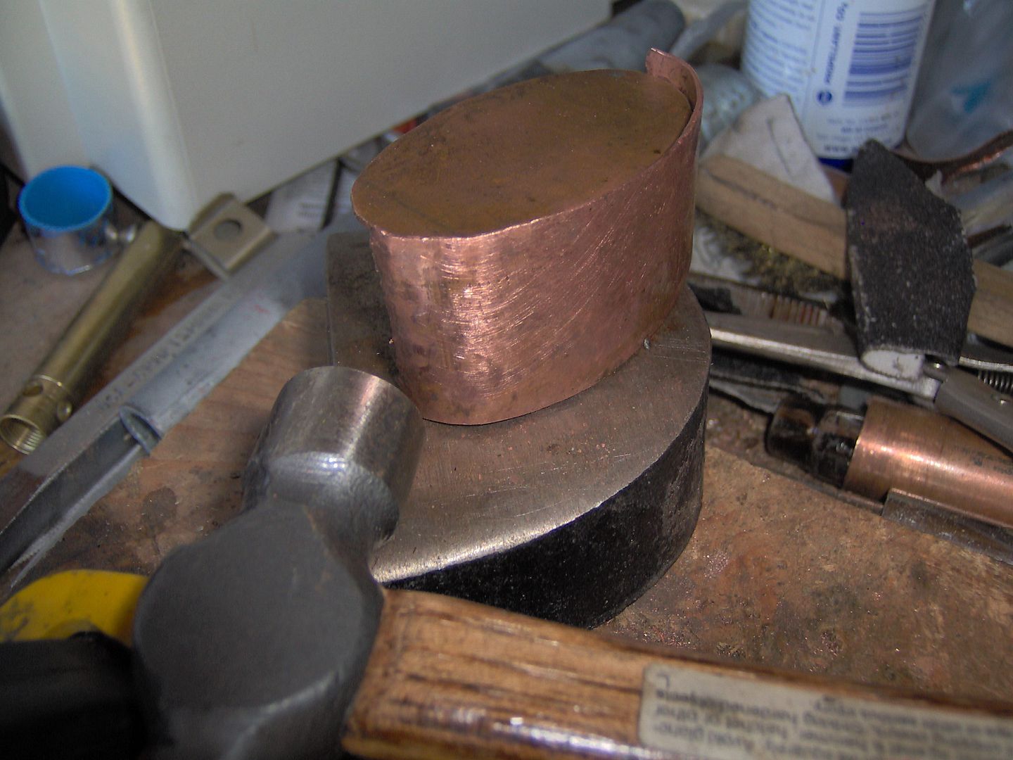
Split some pipe, heat, unfurl with vise grips, pound flat with hammer, cut with left hand tin snips. Repeat.

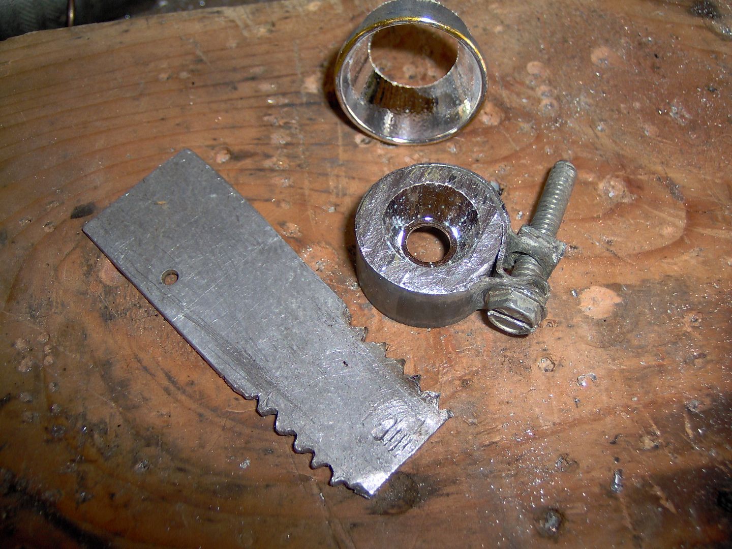
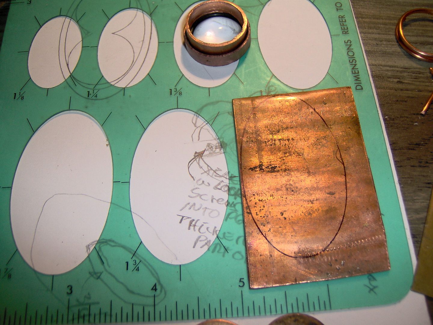
Old school Pickett template. I mean that in a literal sense.

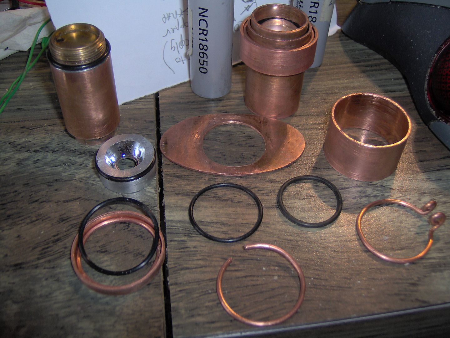
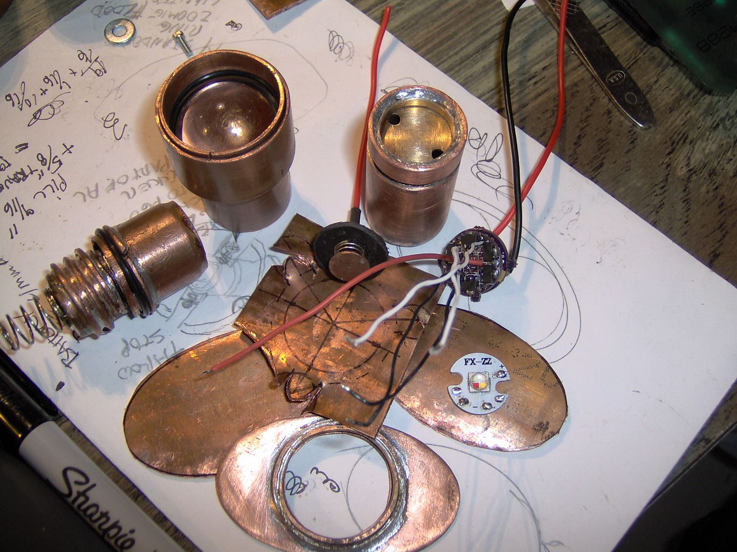
Pill extender (inner tube), various parts, outer tube with head mocked up.

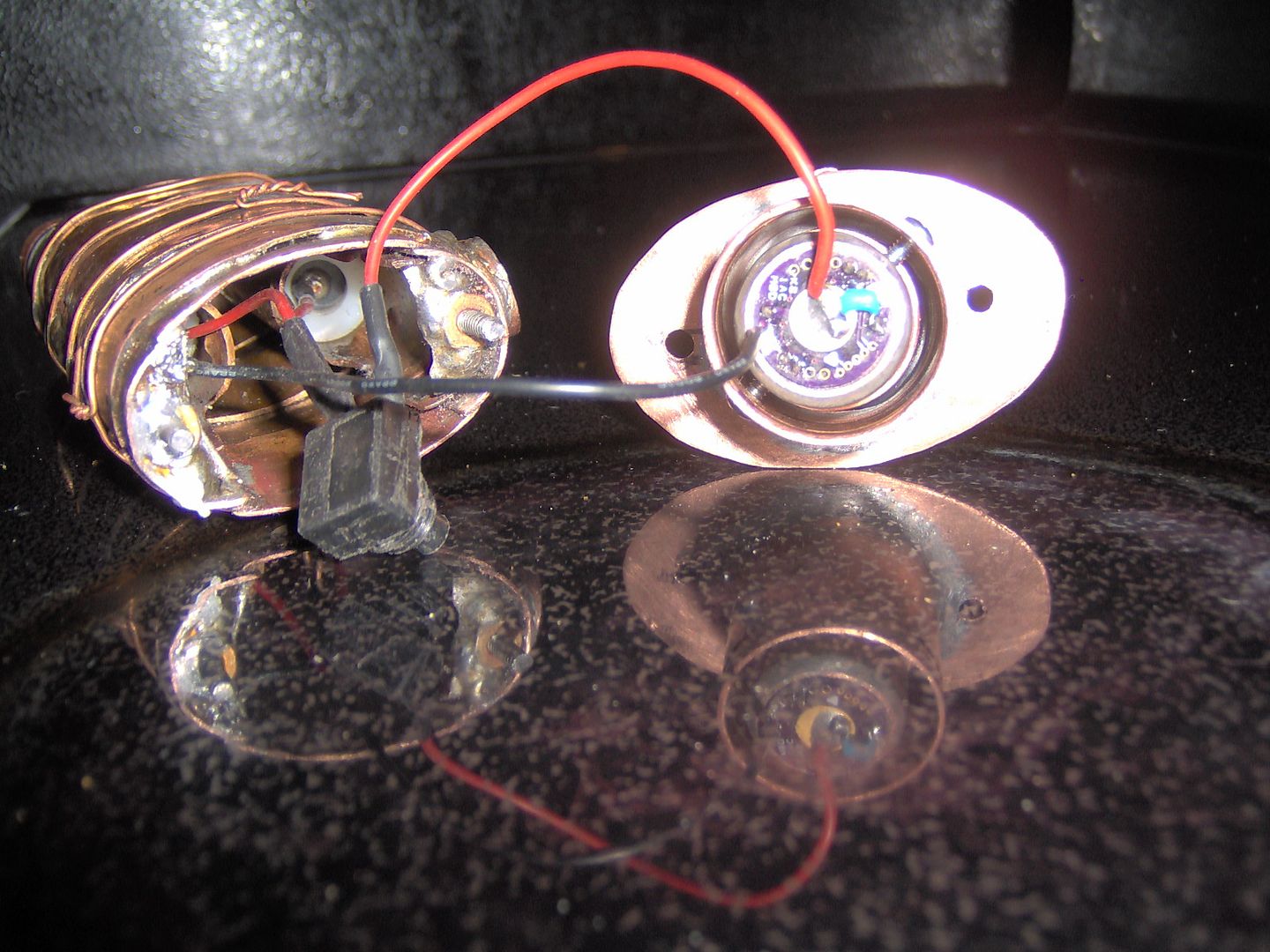
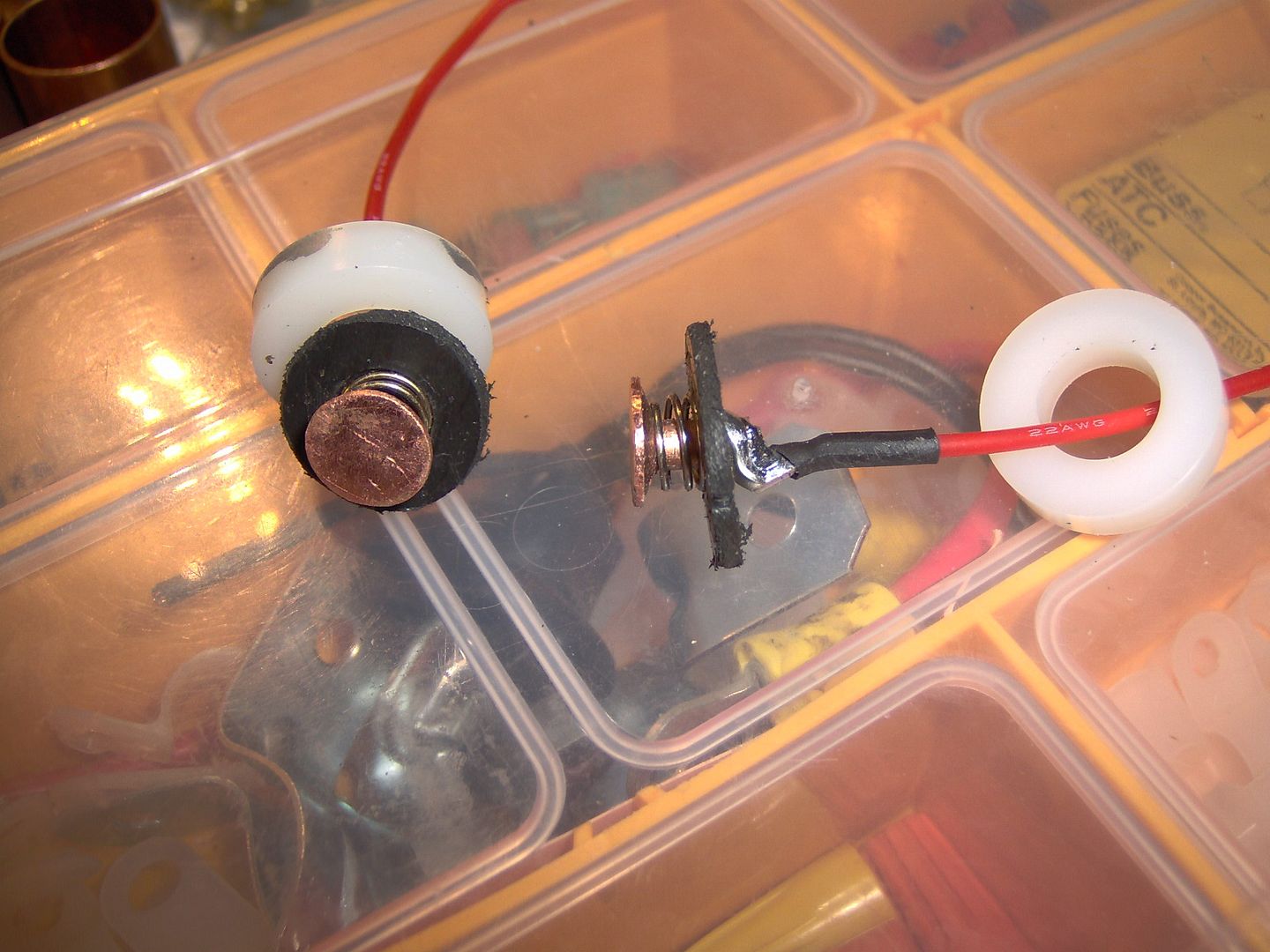
Here I’ve made up the positive contact spring assembly. There’s a trimmed up copper belt rivet, cutdown positive P60 spring, some abs from the salvaged 18650 battery holder, and a bent ring terminal. This will be a big help for the salvaged NCR18650 laptop batteries that I’m going to use. The battery tubes have been cut and punched to provide a backstop for the 3/8” I.D. nylon spacer.
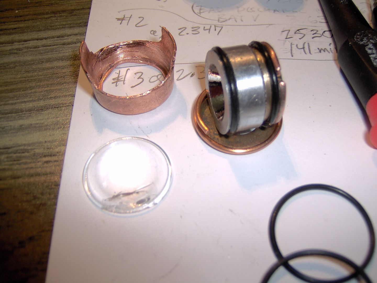
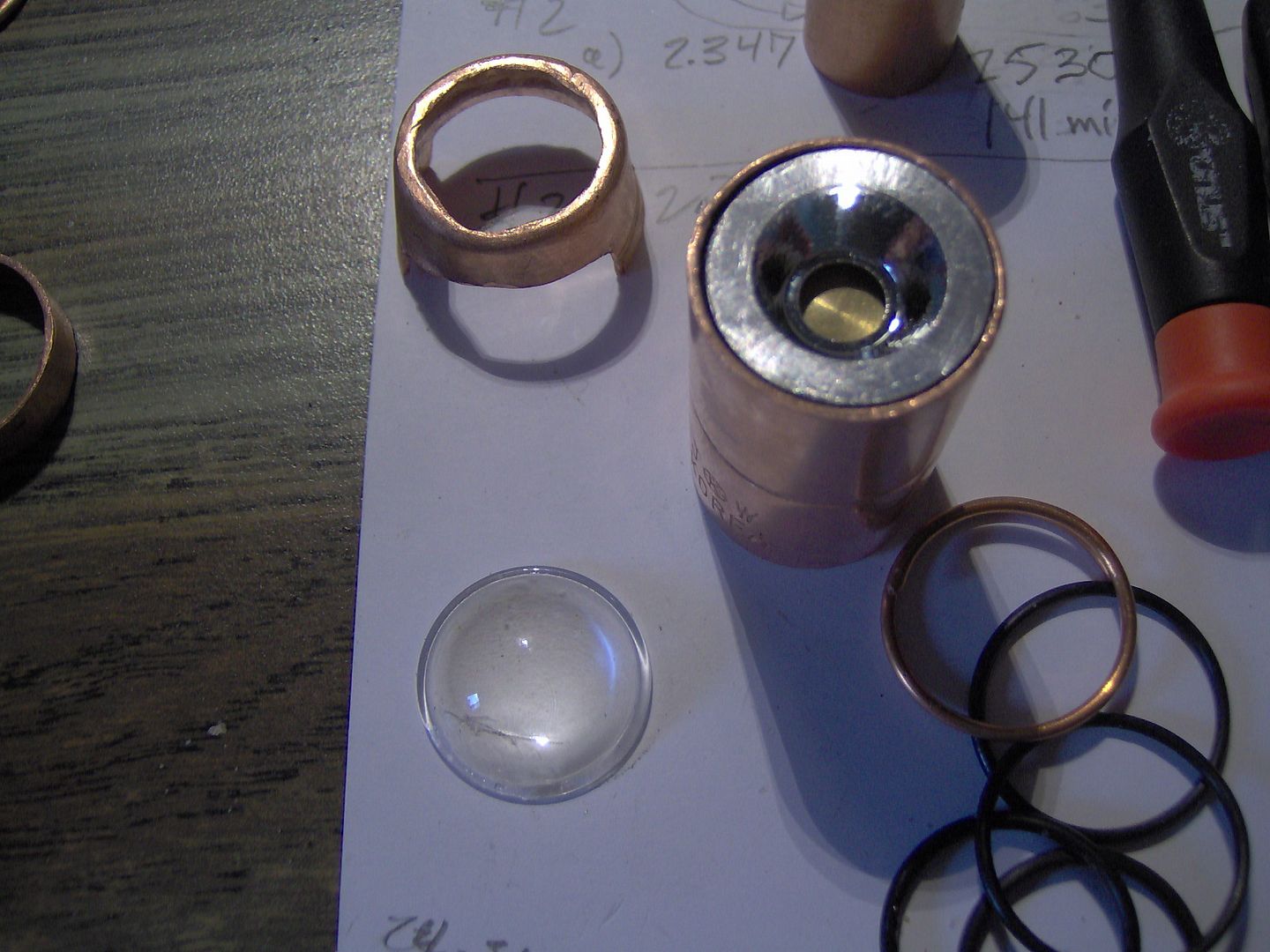
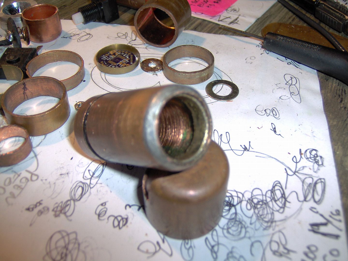
Another parts pic:

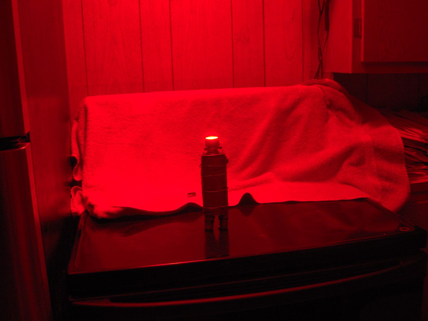
The aspheric replacement is going to be a perfect fit, THANKS Old Lumens! The mini reflector idea had to go, it produced a weird and wide orange peel halo. Think 007 movie intro with the camera shutter effect.

Got a working copy for the tailcap finally, just need to duplicate….oh boy, oh boy :slight_smile: .

Using some wire and small cutoff from 1” coupling for a “captured” o-ring on the top faceplate. That will seal the outer sliding tube.

Have an outline drawn up for fixed plate that will help secure the lens head to the outer tube. I was thinking of using some set screws at first, but I want to have some light pressure on the lens and o-ring assembly.

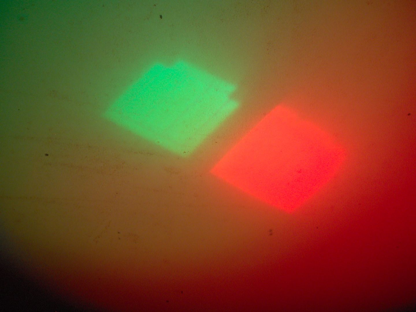
I will be using a Cree XML-Color emitter from Intl Outdoor, with my custom 4x1Amp AMC7135 slave board and micro board stack.

More thought process. I need to get this done, so I can get my kitchen table back!

Now, on to making more copper fairy dust.

……

Got the ballpeen out. What a pleasure to beat on some copper. Getting a little frustrated? Go to Hammer time! Here is the top skirt, it’s going to be split…just because.

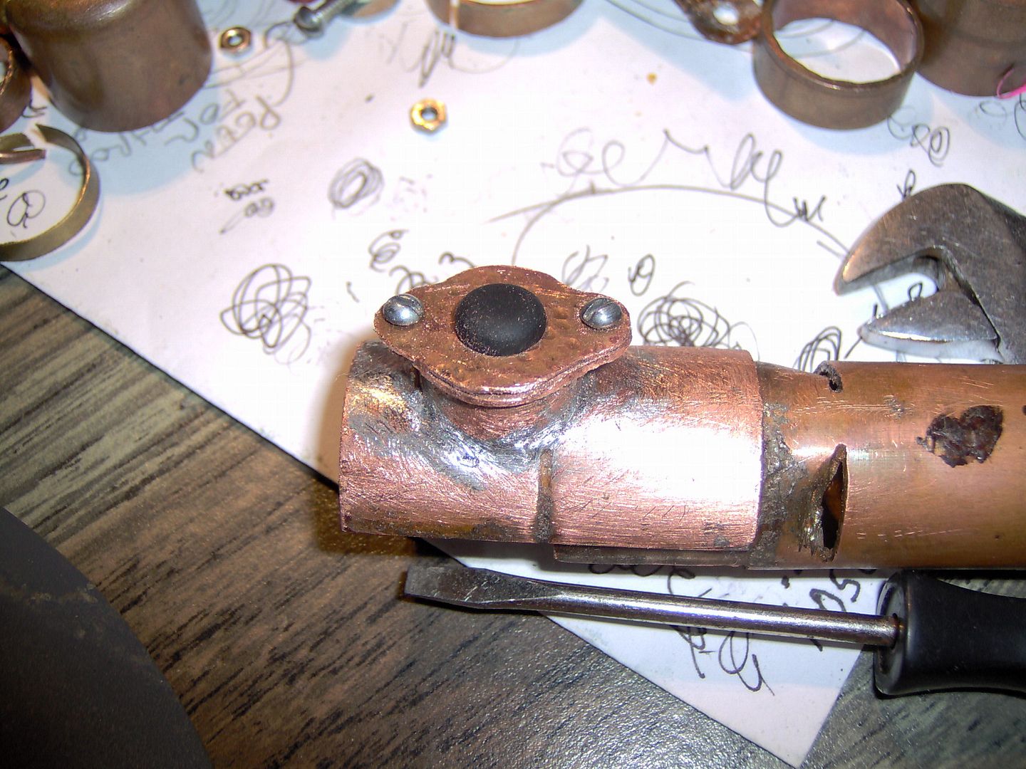
Here is the switch tower that I made for a Judco switch. Also made up a faceplate to seal it off with a small Fastech rubber boot.

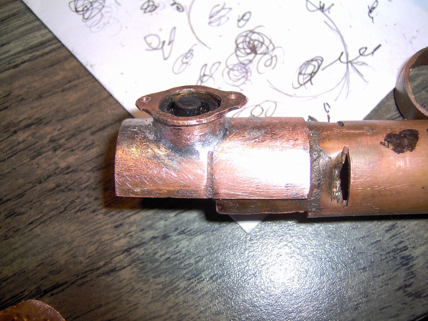
Oops! A different kind of de-doming. I really have to watch how the solder process goes now, and more clamps to hold things in place.

Want to build your own P60 pill? Here is the remote driver end, it goes something like:

  1. 3/4” pipe, insert short 5/8” pipe, and solder.
  2. use rat tail file till 17mm board fits.
  3. snip 0.015” brass shim to fit, press 17mm board till flush, then solder.
  4. if you have a slave board like me then file some more, till 16mm board fits loosely.

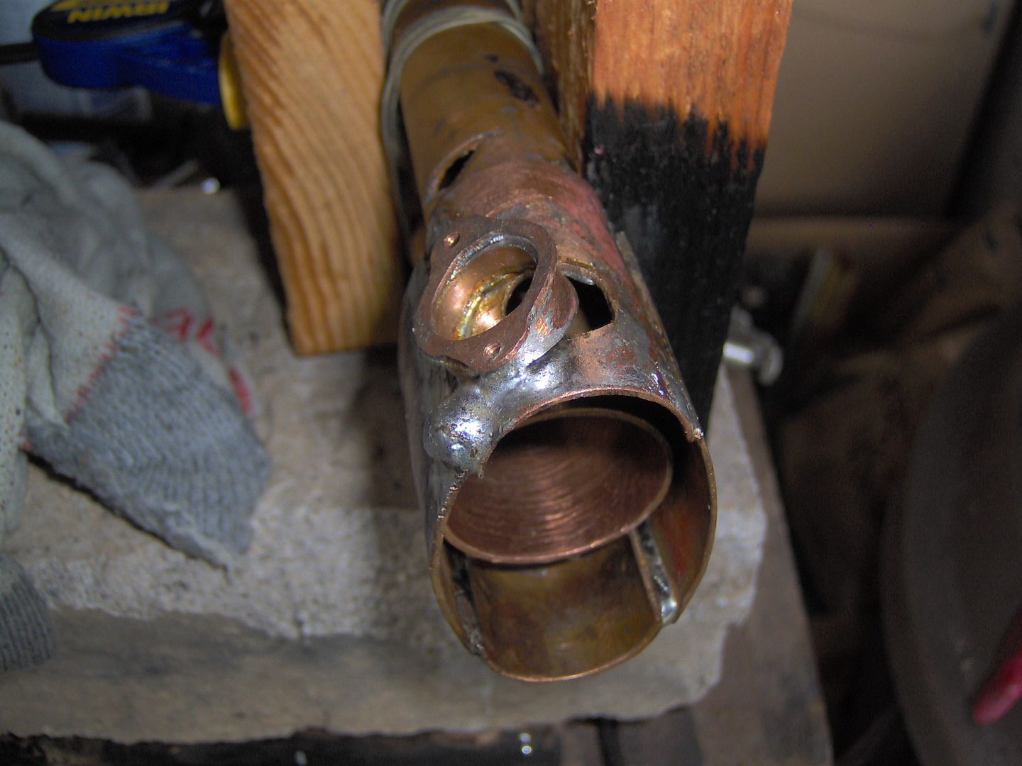
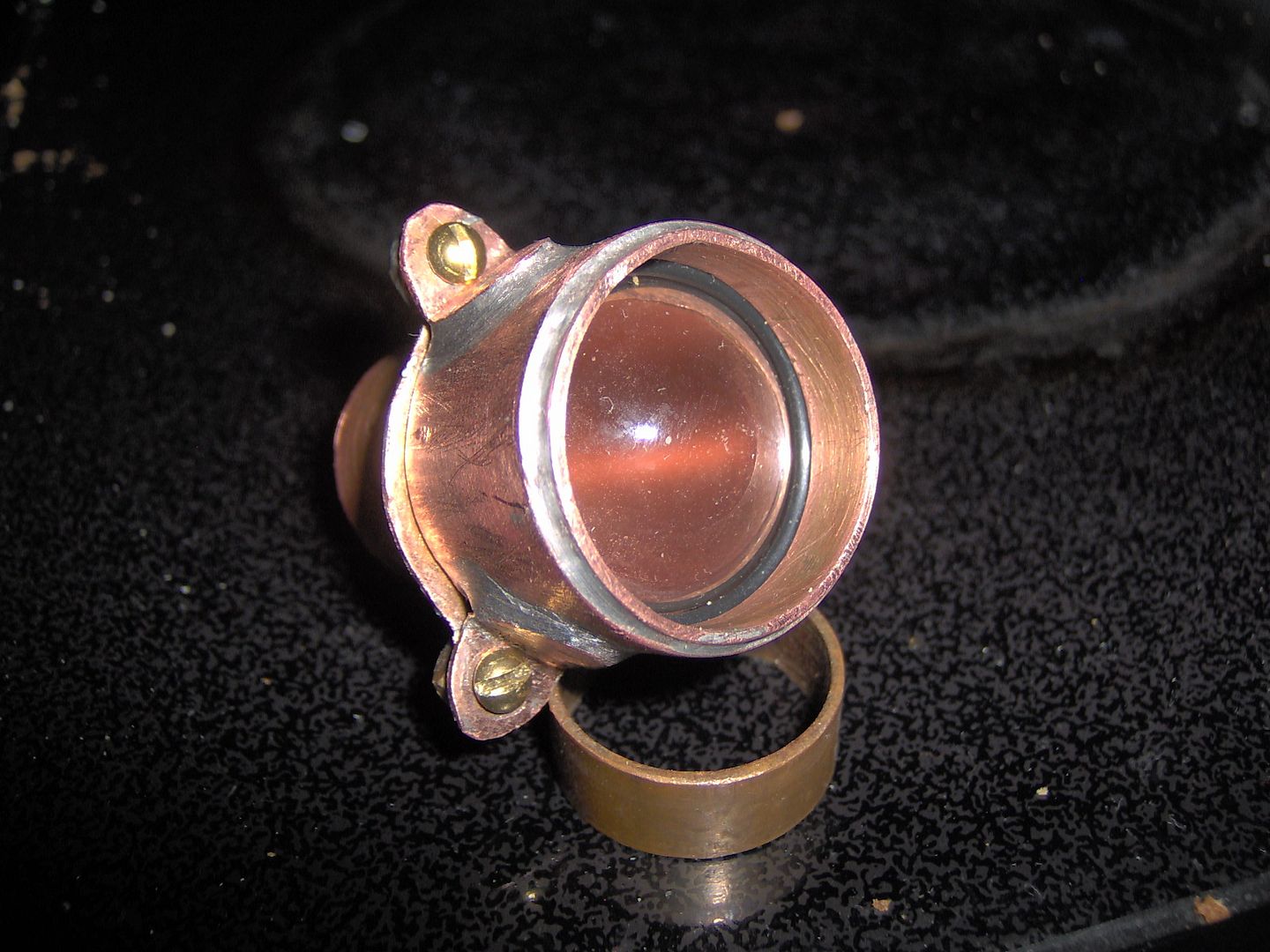
The bezel is done now. Secured head with 4-40 brass screws to anchor plate which is soldered to the sliding outer tube. There’s going to be total of 8 o-rings, with three in the bezel.

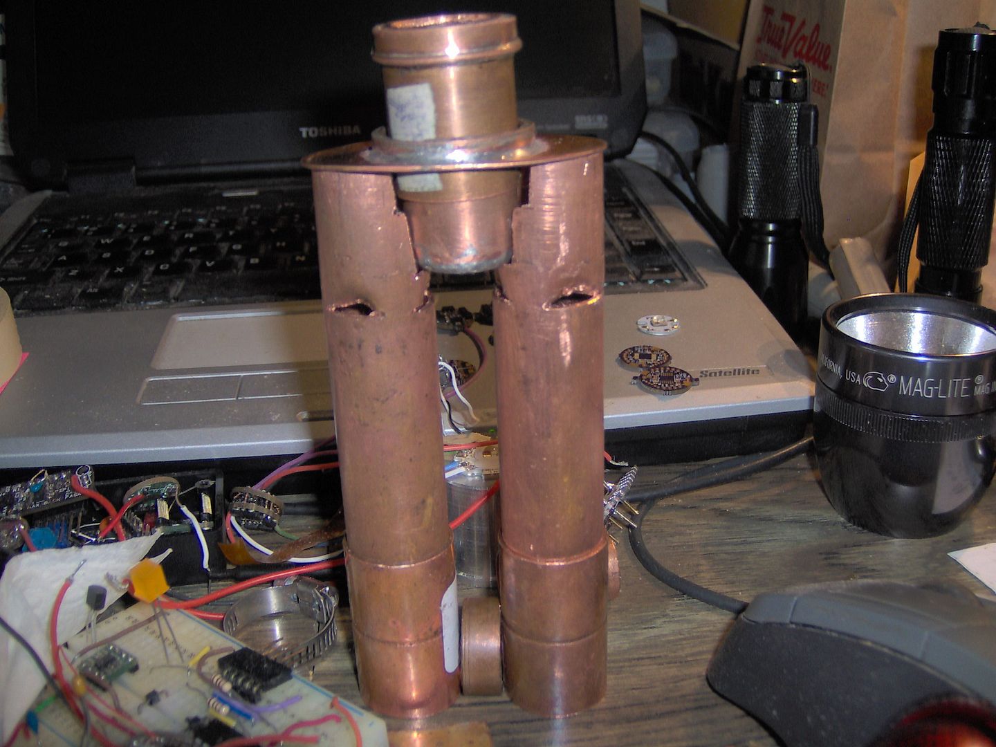
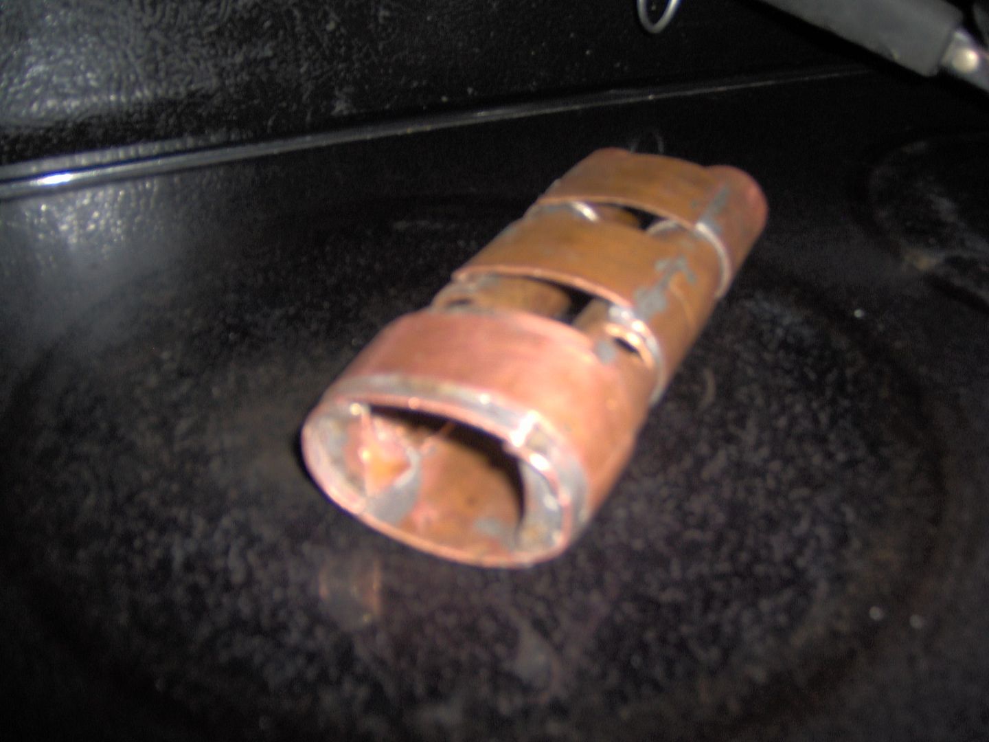
Tube trusses and skin support. Top plate mounting tabs to receive 8-32 screws. The light is on it’s way to recovery from major delamination (or unsoldering) event. This was due to a clamp slipping while soldering in the tabs.

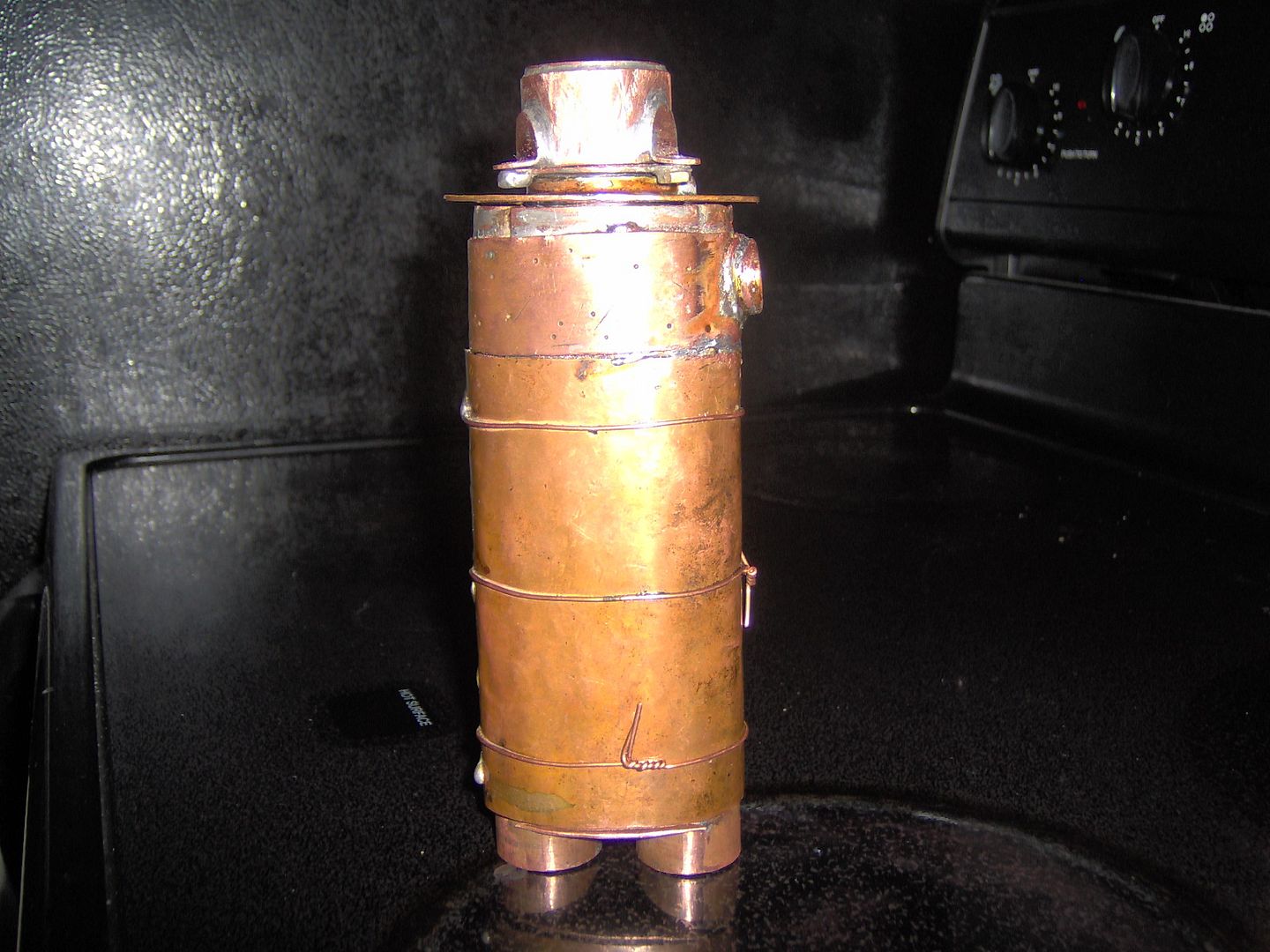
The hammered copper body is starting to take shape. I’m having no problem supplying the antiquing process, intended or not. Stole RBD’s copper wire clinches to keep things together. The wires are staying on till the end (or maybe longer) to keep everything in place.

This thing is getting heavy! The sheer mass of copper is becoming problematic for soldering. When sufficient heat has been applied to solder something, the whole surrounding area is on the brink of letting loose.

Still not done, need to do some more soldering. This would be the last day to take some beam shots, so slapped everything together the best I could, and tried my hand for the very first time. It will take some more practice with my old HP (like 2.1MP old) camera, to get the technique down.

Hook up time.

We have liftoff.

A demo mode video with ramp up/down. As I mentioned before, color mixing isn’t so hot, so this will provide a baseline for fooling around with some diffision schemes after the contest.

Note: couldn’t get the video to stick, I’m going to sleep and will fix tomorrow.

Here’s a link to youtube, not sure how else to do it right now. P.S. The little small dot is some sort of reflection or something and is not visible in the beam.
RGBW vid

There is some spill involved with the zoom when focused on the die. The beam will get smaller, but not focused on the die. Not sure exactly what is going on there, if it’s my bezel or something else that does that?

WSIWYG
What you see is what you get. It works, there’s the beam-shots now in post #2. Not really finished. No excuses on my part, just can’t motivate myself to get out and finish soldering more parts today. The o-ring for the top plate that melted off on me, top plate skirt, and bottom plate is made but not soldered, plus general cleanup, and oh, one of the internal battery cap threads messed up again so the cap goes in only part way.

Hope to finish up in the next week or so, and will share a beauty shot, possibly more beam shots. In retrospect, should have tried grafting some 3/4” hose threads for the battery caps rather than try the homemade threads. The light could have benefited by using a more mechanical attachments, as opposed the layer upon layer of soldering steps.

Want to thank Old Lumens, the judges, the sponsors, other contestants, and the forum for there participation. It has been a truly great experience to share and view all the crazy cool builds they have inspired.

sweet! Copper rocks! Looks like I’ll have to cancel the trip to the Bahamas I was planning to spend my winnings on :slight_smile:

Copper + 1x 18650 + great drawing (little crazy, but I like it) = must be a great flashlight at the end :)

WOW! This should be very interesting. Is that really a thread on that fitting, or are you going to make threads out of copper wire soldered to the fitting? Hammered copper should also be interesting and challenging.

Well if you can keep the pipe and fittings to 3/4” or less, then copper is somewhat reasonable, fancy transitions and such not so much. Which is why I’m going to give making my own threaded plugs out of 14 ga. copper wire. The wire is household romex type from a home project. First try didn’t quite work out, the internal thread pitch moved on me when soldering, so back at it!

Awesome project! We are seeing some extremely creative entries, here!

Lot of hand work going into this one - looks great!

Nice collection off parts your got there. I take my hat off to you guys and your designs.

Flasklite? Please tell me that light comes out one end and booze comes out the other. :bigsmile: Im looking forward to your build.

I appreciate everybody’s encouragement, looks like I’ll need it. The homemade copper threaded end cap build has proved very challenging. Dry fitting is great, everything is all springy and forgiving, but when locked in with solder, it’s got to be perfect, or no go. Going to sleep on it, tomorrows a new day.

Well, flasklite because the end product will look like a flask? Instead of two 18650’s you could use only one, then you would a free tube for some Schnapp’s …

Looks cool. Have you tried sanding to loosen it up? Or some silicon grease?

Foy fully approves of the name "Flasklite."

absolutelyawesomeFoy

More severe than that, I tried a triangle file to clean things up! Mostly it will come to making a jig of some sort that puts the female coil in square and keeps the pitch spacing. If I can find some 3/4” dowel stick laying around, that will be a good start. Then I could solder with it in place, till the coil is tacked in.

Attempts up till now have been fairly close tolerance, need to loosen it up a good bit.

Looking forward to seeing more!

You know how I love using a drill. How about chucking the part into the drill and turning it at low rpm with the triangle file? Might give a better feel for the pitch of the threads.

Added some pics of the P60 build.

RBD I built a thread pitch maintainer tool for female threads, and this worked pretty good while doing the soldering. You can see it in the added pic next to the P60 mod.

Took a bit of a break on the threads, and started in on the P60 mod necessary to fit the zoom function. I am giving up some flood by retaining part of the reflector so I can use the factory relief/kerf for an o-ring. Expanded the kerf with triangle file to fit a 7/8” o-ring. If too much flood is lost, or unsightly artifacts introduced, I will revisit my thinking on this. Also soldered a 14 ga. wire ring to the driver pill, to shoulder another o-ring. This all fits and functions nicely in a 3/4” coupling, and operates very smoothly with a little lube.

Bad news, I chipped my acrylic aspheric lens, trying to horse it into my failed lens cover attempt, (note to self, don’t do that). Will have to order another.

Good news, parts from FastTech and INT Outdoor showed up.

Whaaa… my fingers are getting sore.

What size lens is that? I may have something you can use

It’s 23mm FastTech sku 1187600. I have to back up a little, this a glass lens, and the lens chipped instead of cracked. If you have it, I could send a few bucks, otherwise I will put it in the next order.

I wish I could help you out with the monster copper fittings you need. I saw some good size copper tube up at the second hand store the other day while looking for a 3/4” drill bit. Someone had made a couple grease guns, using 1-1/2” or so copper for the body.

I have a 23mm plastic aspheric lens I can ship out to you. Pm me if interested