The 15Qs have been sitting a while, they were all 4.08-4.09v at the start, the grey Panasonics were just charged yesterday. Also, I only have one meter so I had to change the wiring around between the voltage & amperage measurements, could be something got jiggered. I have big fat wires on my battery box but the leads after that were single 22AWG, and the test leads for the meter are full length, something like 3 feet each, stock Fluke leads. Mostly it's only interesting in showing how splitting the load across multiple cells and the resulting higher voltage affects things.
I figured more than one INR would have killed it dead instantly, I was surprised by those numbers.
Hey, I changed my mind. I just ordered a new MT-G2 for a flashlight built I am going to do when I have the time.
This leaves me with one spare (5000K 6V) for yet another crash-test on a Noctigon board that I may do one of these days. But please give me a reason not to do this test (like: he or she has done that already and the results can be found here, or: relax !, I will do this test for you and I am doing a much better job at it than you do) because I am still reluctant to demolish a perfectly good MT-G2 .
Umm . . . I don't think anyone is going to say those things! We're waiting for you to do it! :) Thanks for these tests by the way! This is very helpful information to many of us!
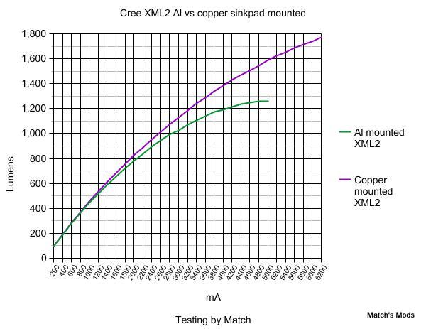
Very nice and useful graphs!
I have bookmarked this page!
Djozz, would be nice have a chart going to 10A or slightly beyond on the MT-G2. You dont have to kill it just for the sake of killing it. But if output seem to continue to rise, then I would not mind seeing what 12A would do, despite not knowing of any drivers that will do that kind of output.
There is not that much point in going far beyond 10A just for the sake of killing it. But it would be nice to know if there is some headroom left at 9A. 0:)
I agree with R86, no need to destroy it. I’m more interested in finding where adding more current results in no increase or a decrease in output. In the case of the XP-G2, this occurred before failure. The XM-L2 was still trending higher when it failed.
This information is very helpful, just don’t feel the need to destroy the emitter if the useful information has already been captured.
I probably would have tried this already if I had a supply with that current carrying capability (6A max for me).
Thanks for your efforts on this!
ok, I don't know what to expect actually, the MT-G2 is a multi-die emiiter, the combined surface area is much higher than a xm-l and the solder path is huge so if the thermal path is built like the xml2 the dies should be able to handle 20+ amps, but if the bond wires can handle that? When the weakest wire goes the rest follow directly because of increased current. Wait and see...
In terms of ºC/W versus area the Luxeon T comes out on top.
LED: ºC-mm^2/W
MK-R: 13.6
XM-L2: 10
XP-G2: 8
Lux T = 5.44
XP-E2: 9
The XP-G2 is slightly larger yet has a higher thermal resistance value than the Luxeon T. The T's thermal resistance is less than double that of the MK-R despite the latter having over four times the area through which to transfer heat. Not sure why the XP-E2 appears to fare worse than the XP-G2 in this regard but I rashly conjecture and am likely wrong that it has something to do with the way ºC/W is measured and the following tidbit:
I just saw this. That was awesome. Simple and to the point; turn it up 'till it blows.
Also interesting that the XM-L2 kept getting so much brighter at higher currents. I was under the impression that anything much over 3 amps went to heat with increased lumens dropping off. Is the upgraded XM-L2 different or am I missing something else?
It just hit me. I already have a xml2 on a copper sinkpad that is reflowed to a copper slug that is reflowed to a brass pill in a Torchlite SV-D2. The light has really good heat sinking. Driven at 4.5 amps the light has no issues at all. Some people have been driving MG-T2’s hard in them.
So, I want to change out the driver and push that xml2, but not hurt it. Any opinions what current I should use? I want to try 7 amps. Is that pushing too close to the limit for this type of flashlight being used outside in hand?
Very roughly, 7A at 3v (XML) is the same power (watts) as 3.5A at 6v (MTG2). Actual numbers will be different and also you have to figure in driver efficiency and a whole bunch of other stuff but that should be enough to get you started.
I’m going to use my go to driver for the first attempt. The Manafont “3T6” driver. People have been resister mod’ing those for multi-emitter lights with good success.
Hmm, 7 amps is very close to the current that blowed the led. Mind that in the test the time at which the led was at that high current was perhaps 2 minutes, no one knows if the led can do the trick continuously without burning through. The temperature in a actual flashlight will be higher too. And I guess there is some variation between individual leds too.
All in all, well, perhaps just give it a go and tell the world
djozz, I managed to repair a single broken bond wire on an XM-L with Liquid Solder from Radio Shack.
Perhaps a very narrow strip of wax paper could be laid on top of the gap between the plates, the liquid solder placed to contact the remaining tabs, then the wax paper removed after it cures? I’ve used aluminum for separation when soldering and it works just fine as the solder doesn’t stick to it.
Don’t recall it being said but the bond wires are brass.
Wow, that sounds like a delicate job well done. I am still curious if the xm-l2 can be driven a bit harder than 8/9 amps with extra thick bond wires, this may be a way to do this :-) .
I am told that the bond wires were gold, but that may be a myth among flashoholics...
 .
.