Thats what I though/was wondering about too when I looked at it…
So far I have just tested it a little… Seemed to work nicely. ![]() I have not attached the antenna wire yet…
I have not attached the antenna wire yet…
Thats what I though/was wondering about too when I looked at it…
So far I have just tested it a little… Seemed to work nicely. ![]() I have not attached the antenna wire yet…
I have not attached the antenna wire yet…
In the whacky world of microwave electronics, that can be perfectly acceptable. What looks like a dead short at DC, can have a totally different impedance at microwave frequencies. That sort of antenna is quite common.
What's the proper way to deal with the connection at the other end, at the driver? Leave the shield not connected to anything?
How would an antenna built like this perform any different than if it used plain wire instead of coax, especially if both conductors are tied together onto the same pad at the bottom as well?
bump!
Thanks to my brother he (we) figured out which AMC7135 is activated in which order.
Number 1 is the first.
Number 8 is the last.
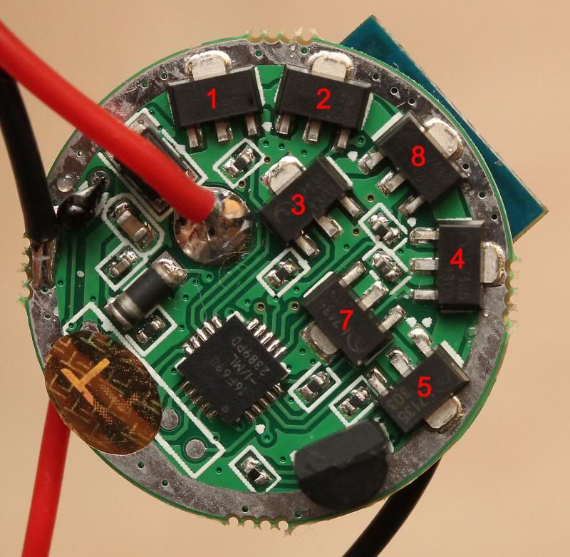
I do not recommend people who are not skilled at stacking to add to this driver in case they mess something up(not the cheapest driver to mess up.).
I managed to mess up the connection between AMC7135 nr “4” and the board or something when trying to add a few 7135s. When AMC7135 nr 4 got activated the board would only activate chip nr 2 , and it would not work again until it was “reset” (lots of half press clicking). If course, it got messed up once chip 4 was activated again…
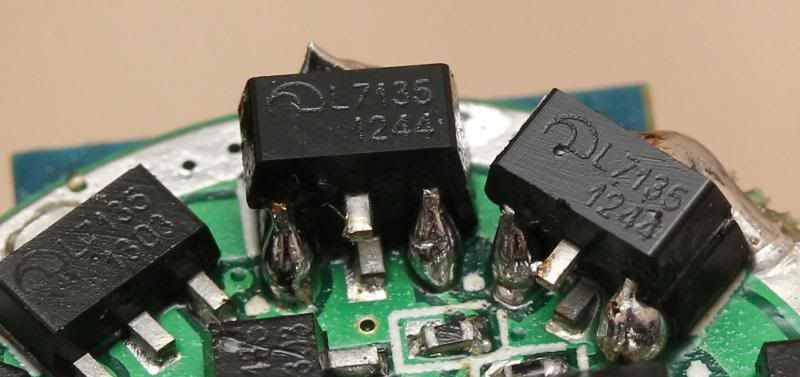
Error was fixed by replacing the chip (despite that the chip worked when tested afterwards). The stacking job looked OK on a close up shoot btw. Chip nr 4 is the one in the middle on the picture below, its under the one I put on top of it.
Either way… Its currently working like it should. Ill probably add some 7135s another day and see how things go. Starting at number 8. Right now, its stock.
I have the first of my two bare drivers rigged up with temporary leads and out in the open air, and no connection problems so far (my only BT-capable device currently is a SGS2). But still using the onboard antenna only, one day I'll find a practical use for it and see if the external changes anything.
I have been thinking about that if a decent amount of 7135s are to be added, it might be beneficial to add several of them to the last activated regulator (nr 8 ) if the driver will handle it…
I have have just played around with my driver that is stock and I though it was working properly again, but I get the error where it goes back to only using one 7135 after it has been on for a while… (probably number 2)
Guess mine was not properly fixed after all… I assume it worked properly when I got it. Did not test it that much then…
Fingers crossed there is still hope for it.
The genius thing about the driver is the ability to program turbo with step-down like you want, and easily program modes below 100% that are still high. But that is not much point when its only 2.8/3 amps…
So far, I have not added the external antenna either. There have been no issues getting a connection (with my SGS2). Although there have been a few times where it failed to connect on first try, then I just press connect again and it works instantly from the same distance and angle.
Do you plan on trying to add more 7135s to one of yours comfychair?
Dunno yet, I'll figure that out once I have picked a home for it. It'll depend on the number of cells and the emitter.
How about something silly, like removing all the onboard 7135s and routing each PWM out to a separate slave board? :evil:
Could you drive a rgb-led with this driver?... I have not looked into the program options, but you may direct every two chips to each mce or xml colour die.
Probably... but the 7135s aren't individually addressable, it only works sequentially. Like, chip 1, chip 1 & 2, chip 1 2 & 3, chip 1 2 3 & 4, etc. You can't do just 1 4 & 7 in one mode, and 2 3 5 6 & 8 in another.
Just curious, is channel 1 the only one that is being PWM’d? Sorry if this answered in one of the many other threads.
Ah, so that would require some thorough reprogramming by the fasttech wizzards.
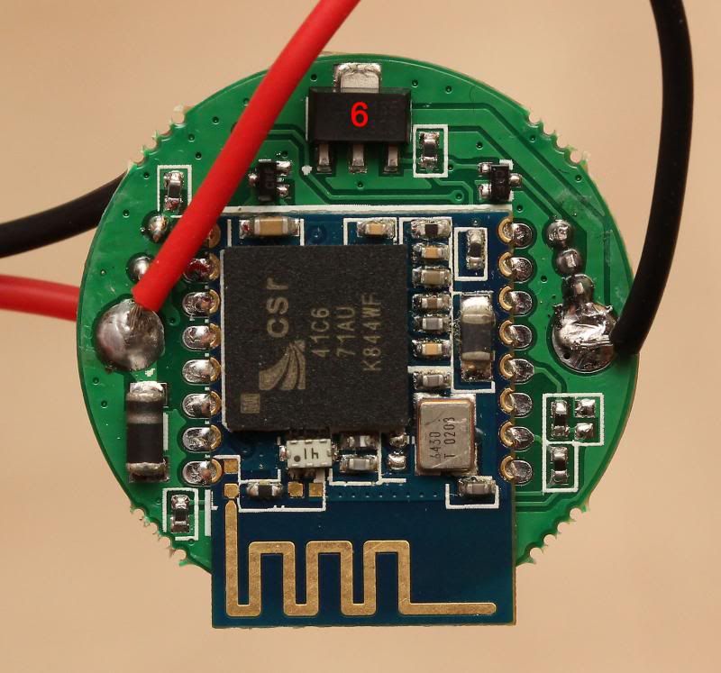
RaceR86: Hope you don’t mind I borrowed your photo & marked ext antenna locations.
https://budgetlightforum.com/t/-/20829#comment-452245
No problem.. :)
I'm about at the end of my patience with this thing... has anyone had the issue where the driver won't enter programming mode?
edit: Disregard, I accidentally dropped it on the floor then a big hammer fell on it several times.
hahaha.. ROFL... Im sorry to... Congratulations, probably a wise decision...
Mine have been collecting dust since I played with it. I lost all patience after stressing with it for hours. I plan on see if I can get it up and running decently again some day. The wise thing would probably just to have one of those accidents.. 0:)
It almost seems like we were the only ones who bought these drivers. Did anyone else buy it?
Did you actually make anything out of any of yours? Did you successfully increase current and get it to work properly?
I had it completed, in a 3D Mag. Tested many many times along the way and everything worked fine. Tested after mods to the driver itself, tested after checking fit in the pill (required a lot of machining), tested out of the light after the pill was absolutely completely finished and all was fine. Then, somehow in the process of setting the pill in the tube and tightening the grub screw it 'forgot' how to go into programming mode. The fit was excellent and there was nothing about installing the pill that could have affected the driver.
Switch on, wait 5-6 seconds and turn off then on and it should give 3 very dim blinks, pause, 3 blinks, pause... to indicate programming mode? No, instead of the 3 blinks it just went to a steady moonlight mode (a mode that was not in the profile I had loaded at the time), and of course no more programming mode. Very strange and makes me reluctant to try again with the spare driver that still works (well, it worked yesterday, can't say if it's had a problem and croaked since then while it's been sitting doing nothing...)
Stock output?
Yes, nothing altered function-wise. The transistor was flipped to the opposite side of the board because of space issues, and I used .063" copper between the main board and contact board to keep them in alignment when installed. Onboard antenna was snipped off also because of no space for it. Bluetooth worked after the antenna mods, I even loaded a new profile and it all worked wonderfully. I even tested the connection range afterwards out to about 12 feet and it worked fine, it may have worked farther than that but I didn't try it. I even re-tested all those same things after the pill was put together for the final time but before it was dropped into the tube and it worked.
I even deleted all the pictures of the build it made me so mad. Wish I could delete it from my brain too...
Ok, thanks for the info.
Do not try to fix the pictures in you head with a hammer. Otherwise..
