Based on the test above, I dared to make a 2x18650 direct drive flashlight mod, and here are some results.
I must admit that I wrecked the light already, the reflector was electrically insulated from the solder connections and led by a piece of Kapton tape, I screwed it too tight, the tape moved and the plus and minus shorted via the reflector somehow, frying the switch. Have to order a new switch now and find a better way to tighten the reflector. But this all happened after I tested the torch out, so it might be interesting to see the results. EDIT: I repaired the light by bypassing the switch, see post#36
I took this torch that I bought on sale from cnqg a while ago:
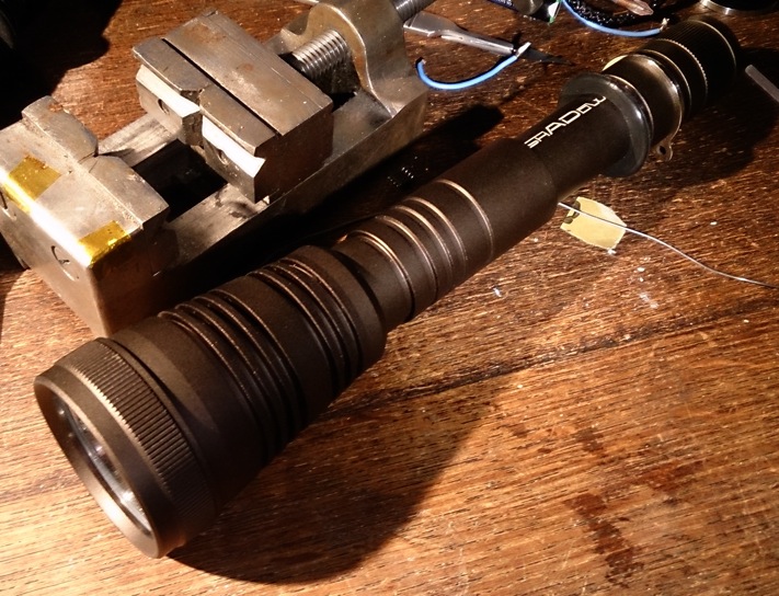
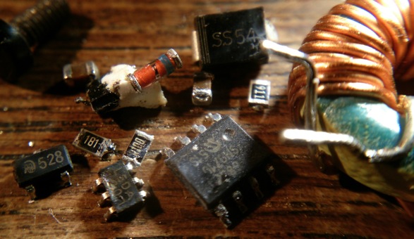
It is the Shadow TC 300. I removed the driver and led board, cleared the driver from components to use it as a contact board. I tried to make every electrical path nice and thick for handling big amps. Soldered the minus led wire around the corner of the contact board directly to the brass contact ring, soldered some solid copper wire through 4 via's of the positive battery contact plate and soldered the plus-ledwire to that, and used copper braid to enforce the conductivity of the + contactplate spring:
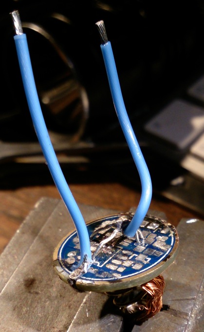
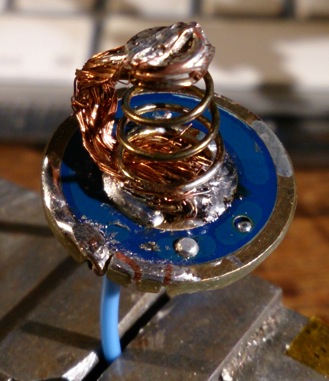
It doesn't look pretty but it sure can handle some amps  .
.
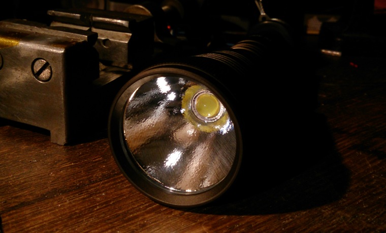
So here it is with the MT-G2 on the Noctigon in place. A weak spot is the reflector directly screwed against the top of the led itself, ruining the thin layer of silicon around the dome, it does not ruin the performance of the led, but eventually after screwing it too tight the light shorted somehow. The tests were done already by then.
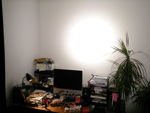
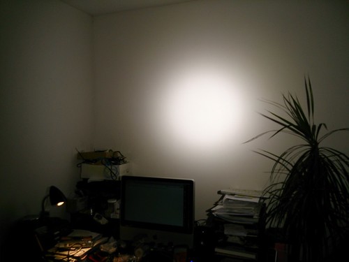
The first thing I did was to put some fresh loaded Panasonic CG18650CH (IMR) cells in it, and measured tail current without switch: 8.5A . I decided at that point not to improve the conductivity of the switch spring with copper braid, and measured with the switch into the circuit: 5.6A, that is more acceptable to me . I took a beam shot from three meter from the wall, the first is how it actually looked the second one is underexposed to show that it actually has a nice hotspot:
Here's a video of the first two minutes measuring ceiling bounce lux. Multiplied by 20.9 it gives a lumen indication (so at start that is 2970 lumen). I stopped the test when the head got too hot to touch.
The smoke coming off the lens are evaporating fingerprints that I forgot to wipe away  .
.
In the middle of the night I dared to film a very quicky beamshot into the neighbourhood, it is over before you start paying attention :
After some playing around I became a bit more confident about the light, charged the batteries to full again and did a stamina test of 10 minutes at room temperature without extra cooling (even not with my hand). I measured the output:

Afterwards the light was way too hot to touch, but not blistering hot. The batteries were also hot but not that hot, the voltage was 3.74V each.
I also checked some protected no brand Li-ions (non-IMR) that came with a very bad headlamp I had to review (EDIT: removed some unneccesary grumbling  ), and it still runs at 4.6 A on those (initially).
Concluding I must say the MT-G2 runs quite happily on two 18650 IMR's direct drive. Now I have to repair that switch (or I may not do that and go back to small EDC flashlights where my heart lies ) EDIT: repaired, post #36
Hope you like the results, and that the information is somehow useful to someone.
 )
)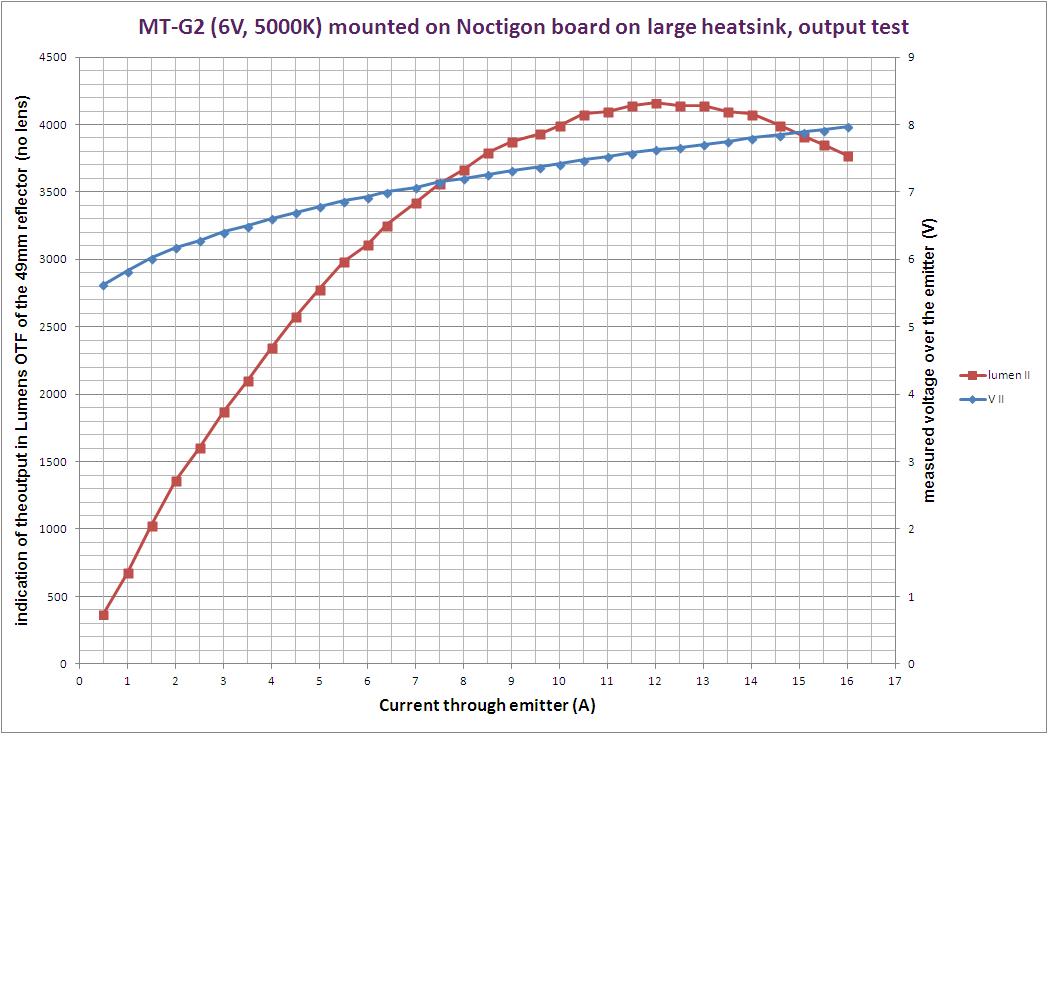
 . The led alone will produce -apart from emitted light- about 30W of heat at that current, so the build needs a good thermal path and sufficient surface area on the outside of the light.
 .
.
