28.07.203
-There was an issue with the analog voltage adjustment in my power supply, that explained my issues with it. Now that Im aware the issue, I can adjust it accordingly and that makes testing the driver easy. Some findings.
-If I “turn down” the trimpot the stock driver seems to output about 2,15A to an MT-G2. So quite similar to an XM-L in terms of output if using it stock.
-When the driver is adjusted for around 3,08A to an XM-L it will output around 3,3A to an MT-G2.
-If the driver is adjusted for say, 4A to an XM-L it will still only output around 3,3A to an MT-G2 with fresh NCR18650B batteries. If using (protected) 18650PD, ill get up to about 3,5A. Unprotected cells and optimized springs will probably get you a little higher.
-If input voltage are 9,14V I was able to output 4,1A to an MT-G2 if the trimput was adjusted for about high/max output. That was the max input voltage i tested it with.
-The driver can be adjusted for up toward 4,5-4,6A to an XM-L before it drops down to about 4,1A.
-The driver can be adjusted for up towards 5+A to an XP-G2 before it drops down to about 4,1A.
-The driver gets very hot if adjusted for max output.
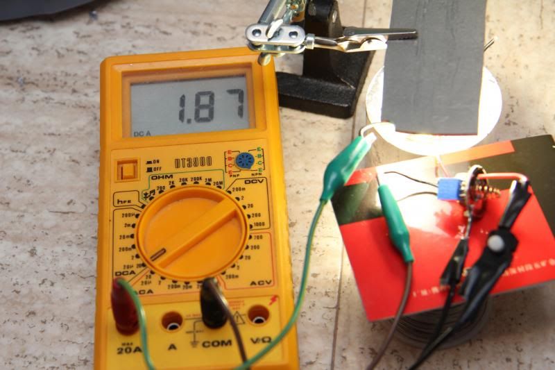
-If the input voltage is down to about 7,1V, the driver will only output around 1,8amps to an MT-G2.
My conclusion based on this:
If you want 3A+ to an MT-G2 then that can be easily achieved with a simple resistor mod/trimpot. You might even see 3,7A+ amps with the right unprotected batteries and mods at startup.
Once input voltage starts to go down output will decline. Basically, it will not not stay well regulated with an MT-G2.
Driver does not seem to be well suited for 4,1+ amps to an XP-G2, XM-L, or MT-G2 when using a trimpot. (I don’t see how various resistors could do any difference.)
Driver can easily be adjusted for close to 4amps to an XP-G2 or XM-L. I can not comment on reliability.
I think an MT-G2 deserves at least 4 amps. So I will not use it in this light.
26.07.2013 2nd update
Upping the juice?
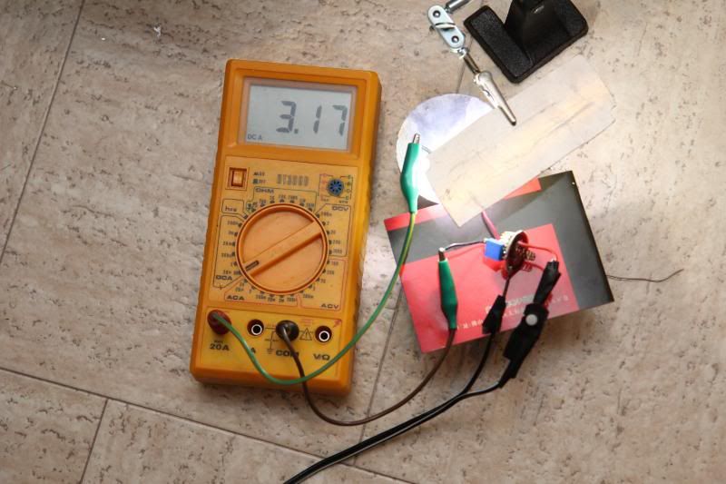
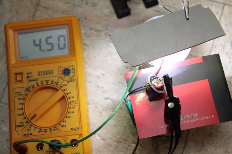
Test setup. Used a power supply.
Earlier this was trimpot modded to 3+ amps to the emitter. I checked with XM-L, 2,98-3,17 amps to the emitter depending on input voltage from about 5-8,4. In this case, emitter current was higher when input voltage was less. Basically, XM-L + 2x18650 + that driver circuit = full output on high all the way til batteries are fully drained.
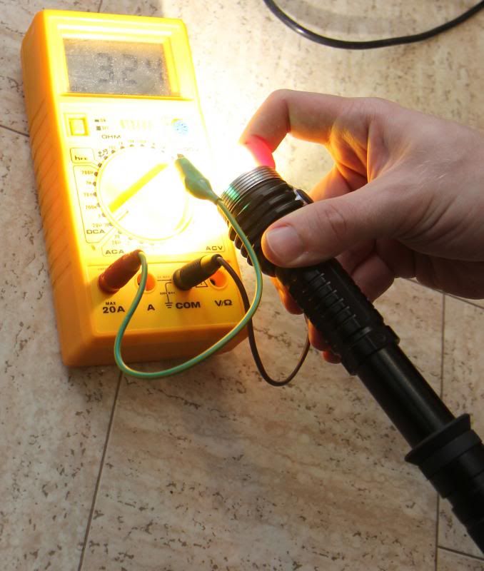
Same setup with MT-G2… WHAT?? Where did my amps go? Yesteday I saw 3,29A when I tested it in the light and with same setup.
Put the light back together with the MT-G2. There they are. 3,24A at startup, that went quickly up to 3,3A with the MT-G2. I cant explain it, never seen it happen before, but for some reason it seems like this driver combined with my MT-G2 and my power supply is not a good combo?? Never seemed to have issues with MT-G2s and these types of currents before. On afterthought, maybe its the switch I used??? :~
Well, I wont let that stop me. Time to let the juices flow and crank up the trimpot! J) Ill just do the testing on the XM-L then.
4,59A seems to be about max for the driver circuit in my light, if I try to go higher Then it goes down to about 4,09. I set it to 4,5A first, but that seemed to be to close to the limit where it would easily go down to about 4,1A. I dialed it back to 4A. But depending on input current and how hot it was it was sometimes uptowards 4,1A. I dialed it down to about 3,8 –3,85A with the XM-L. Just in order to be “safe”. Not sure how safe the setup is though. Driver circuit still heats up fast!
Maybe that will give me 4A to the MT-G2 since the previous setup had higher output to the MT-G2?? 0:)
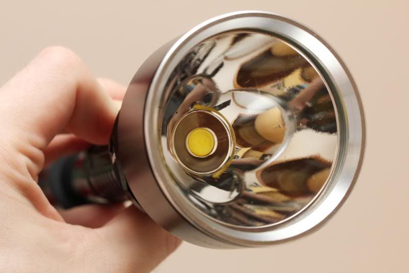
(re-use of picture). No gain was seen when testing on the MT-G2! ![]() :~ :_( It was basically like it was before i tried to get higher current.
:~ :_( It was basically like it was before i tried to get higher current.
As far as I can tell based on all this, 3,3A seem to be about max output to an MT-G2 with this driver circuit.
Now I am seeing about 3,7A at the tail. I believe the resistor mod is currently pushed too far (for an MT-G2). Output to the emitter does not get higher with an MT-G2 , but input current seems higher. I believe it was considerably lower than 3,7A before I tried crank up the juices even more.
I should do more testing, especially some testing with lower input voltage. Generally 3 cells are recommended in order to drive an MT-G2 with constant high regulated output. Im not sure how much emitter current will drop when using this driver in combination with MT-G2. Maybe others will test it.
With my close to zero electronics skills I would say 3,3A is the limit to an MT-G2 with this driver circuit. If I decide to keep and MT-G2 in this light, Ill dial the trimpot several steps back. At the moment, I only have this one MT-G2, and I am working an a more exiting project for that emitter… J) 0:)
26.07.2013
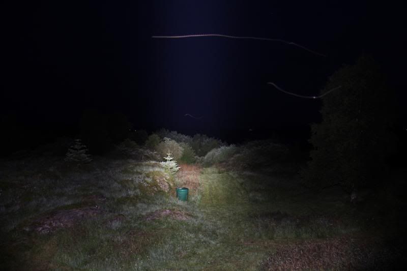
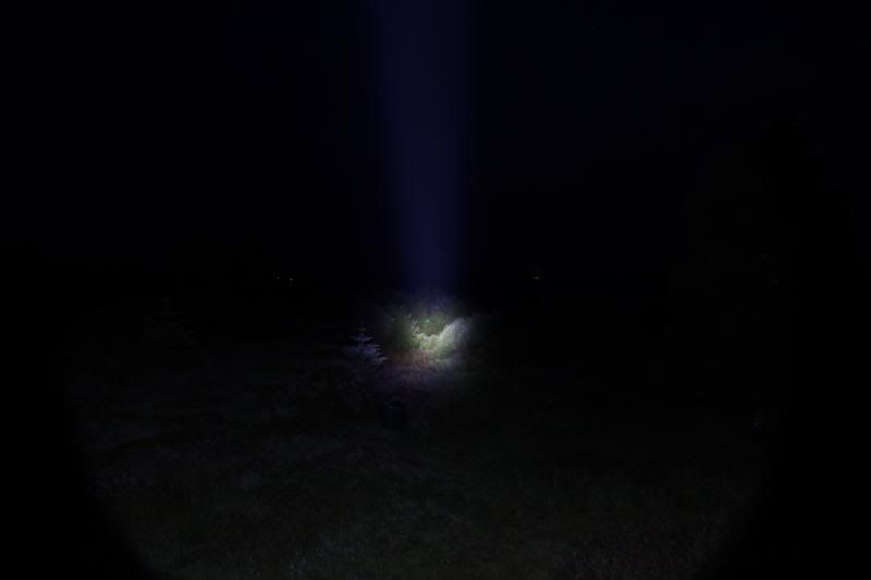
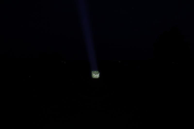
Beamshots. White balance was set to auto, so differences in tints are not properly showed. These pictures are taken with wide angle (17mm on APS-C).
9 XM-L fandyfire. About 74 watt (with fresh batteries)

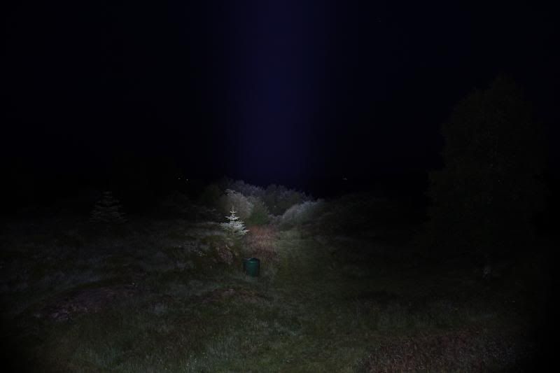
SRK, modded to 3A+ to the emitters and NW XM-L2 (80+ CRI). 30+Watt
ZY-T13 MT-G2 @ 3,29A. About 21 watt
UF-X6S, 5 amps to NW XM-L2 (80+ CRI) About 18 watt
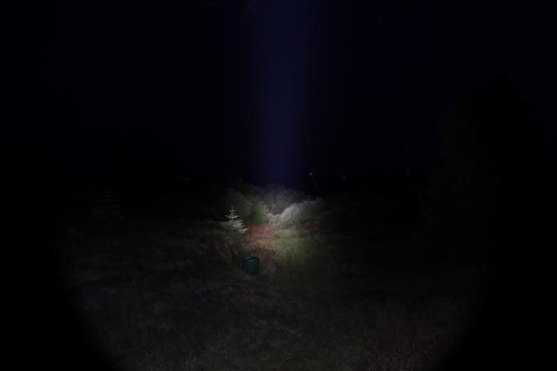
ZY-T619 with 4A to a de-domed XM-L U2. About 14 watt
N-Light XT50 (aspheric zoom light), 3A to a de-domed XP-G2. About 10 watt.
25.07.2013
Some time back I modded my ZY-T13. I was inspired by this thread:
Modded: Small Sun ZY-T13 3.2 Amps or Sunwayman T40CS Clone.
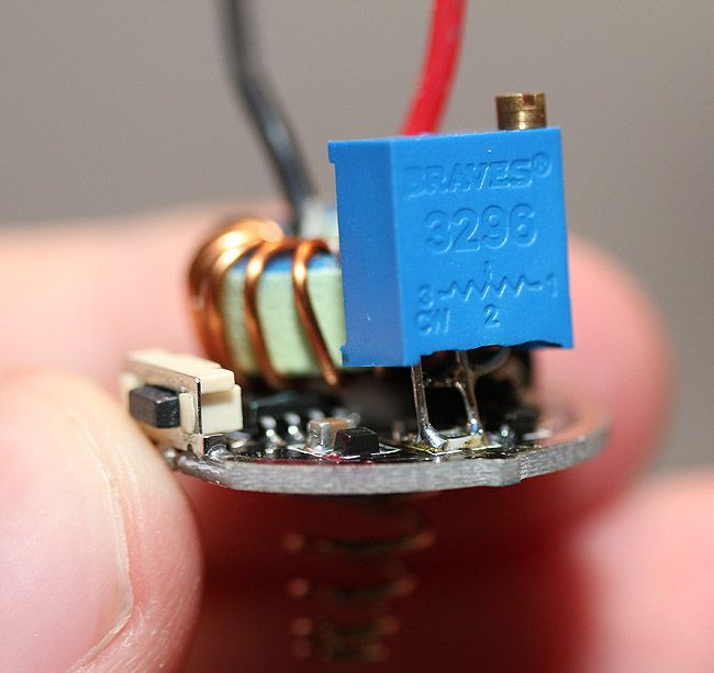
I made this post. It was one of my first mods and my first thrower. I put on a trimpot (did not have any suitable resistors then) and used a crappy setup to adjust it to 3+ amps.
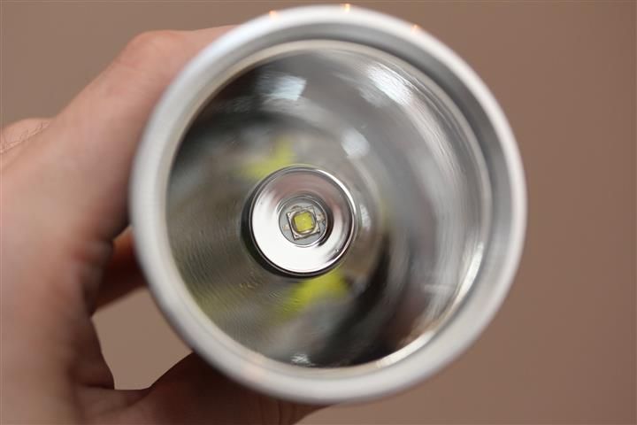
Later I put in and XM-L2 on copper…
Since then I have gotten several other throwers, and my ZY-T13 was not the best in terms of throw, tint, or anything. I was thinking about selling it.
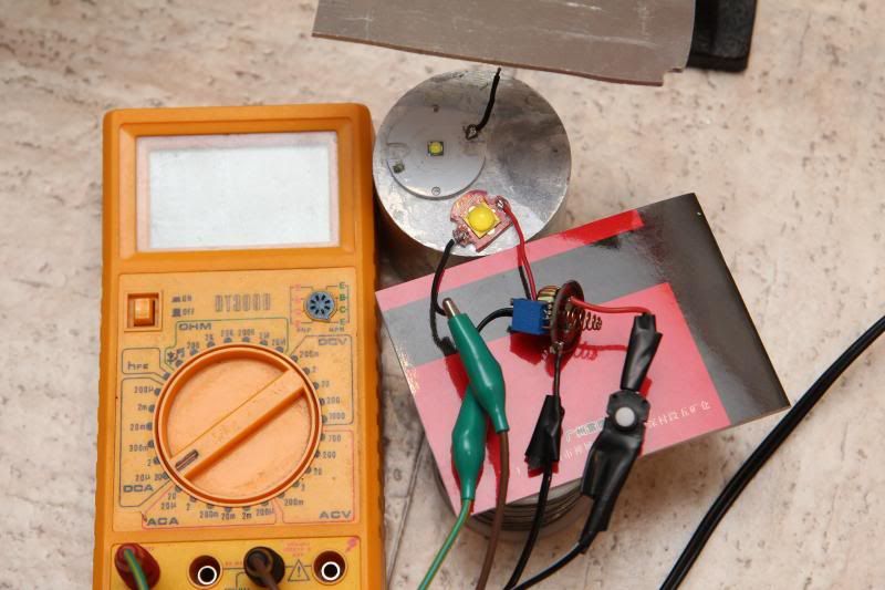
Today I saw the CRELANT 7G5MT MT-G2 P0 NOCTIGON 2*18650 FLASHLIGHT.
And that got me thinking… “I have one of those emitters” ![]()
A little later…
I measured 3,29A on the emitter.
Ill get back to beamshots and such. I have barely used the light, but based on first impression I like it better, it has much less throw, but it puts out a lot more light. Beam is nice too.
I need to make the pill nicer though, because its not 100% flat and had a tiny dot of aluminium sticking up in the middle.
Anyone know how much further this driver circuit can be pushed? 0:)
I need to do various testing, more updates to come…