i thought of that too, if the same LED is used for all single LED drivers then it makes the tests a lot more comparable and we can discern slight anomalies in drivers when comparing different tests
Can i also suggest the Qlite 3.04A driver to test, i assume it will give identical current shifted results to the 2.8A 105C but it would be nice to have confirmation
That is completely reasonable
I was thinking it would be a massive undertaking, but a chart of voltages for XP-G, XM-L and XM-L2, i have long suspected different tints have different forward voltages (and maybe different bins might as well for the same tint), however instead of testing doens of chips, how about a few common ones, an XP-G2 R5, XM-L T6 3C and U2 1A and U3 1C, and XM-L2 T6 4C and U2 1C
i had the same conversation a few hours ago with another forum member, there is even an off chance you get a high end of tolerance T6 and a lower end of tolerance U2, we would never know without several of each chip tested.
Perhaps a similar test, 3 to 5 XM-L2 U2 all the same tint just to see what the forward voltage is, or perhaps any chip of the same bin/tint that you may already have
It has similar specs, nice modes and is smaller. Most interesting: whereas the LD-29 seems to underperform in single cell mode (only 2,5-2,6A), this is not mentioned with the LD-2C. So there’s still hope…
If you could test both, LD-29 and LD-2C, in comparison and in both voltage-ranges, would be great.
I’d gladly provide you with my new, unused, untouched LD-2C from IOS that came the other day. PM me your address if you want to use it. I wanted to fiddle with it myself but your rig is much better and results are comparable that way. Or PM me your PP-address, I second the idea of Matjazz.
Again, thanks for a good, informative report.
Strange that you have a 3.04A variant of the 105C. A variant that Fasttech should not have in stock (8x0.38A).
Thank you HJK for doing all this work! Your results for the Nanjg 105C confuses me though, could anyone please help me understand what’s happening here?
I have read forum members here (Old Lumens springs to mind for one, when he was modding the 3 and 4 AA to “D” battery carriers) trying to use three AA Eneloops to achieve 2.8A at the LED and finding that they weren’t getting anywhere near 2.8A but, when they used four AA Eneloops, they hit the 2.8A easily, and it remained “regulated” at 2.8A for a reasonable time.
Their driver would have been seeing something roughly around the 4.8 volt mark from four Eneloops under full load, but your graph shows that by 4.5 volts the output has apparently dropped back down to 1A? Why do your results differ so greatly from their real world results? Is it really just due to the heat build-up of the driver you tested?
This exact driver is rated from 3 to 4.5 volts. I realise that 4.5 volts is not their ideal input voltage, and a lot of that will get burnt off as heat, but why would it be rated to 4.5 volts if it couldn’t produce the required current at that voltage?
Please understand I am not trying to devalue the work you have done here!!! I just can’t quite make sense of it all.
HKJ, Did you get a sense for how fast the 7135’s overheat when not properly heat sinked?
I know it would depend on a lot of factors, but just wondering how fast current would drop in a worst case situation after light if flipped on with fully charged cells.
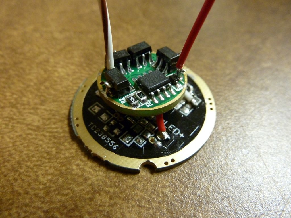
benz, the sag at higher voltages is likely due to heat. The driver is floating in space with no thermal contact. In a flashlight, the driver ring is sitting on the pill and this conducts heat away from the chips. The thermal tabs (big Gnd pin) is right there on the edge which will make a huge difference in board temperature.
With the drivers floating in the air there is very little cooling for such a small pcb, I believe that it overheated in maybe 30 seconds.
Mounted in a flashlight with prober contact to the aluminium, it will be much better.
This is one aspect that I cannot test properly. Even if I mounted a piece of aluminium on the driver, it would not be a prober test, because the actual cooling will depend on the actual flashlight and how it is mounted in it.
38P is 380 mA. That’s why you get around 3.0A in your measurements.
I wonder if all of their stock of that sku number is in fact 3.04A drivers. That would be an opportunity.