FandyFire K2 (1x26650, XM-L U2)
Reviewer's Overall Rating: ★★★½☆
Reviewer's Mod Host Rating: ★★☆☆☆

Summary:
| Battery: | 1x26650 or 1x18650 |
| Switch: | Side, Electronic |
| Modes: | L 20%, M 50%, H 100%, hidden Strobe and SOS, no memory |
| LED Type: | Cree XM-L U2 (est. 1A or 1B tint) |
| Lens: | AR Coated Glass |
| Tailstands: | Yes |
| Price Paid: | Review sample from DX, reg. price was $29.90 |
| From: | DX |
| Date Ordered: | N/A |
Pros:
- comfortable to hold, fits well in the hand
- Good heatsinking
- Large emitter star
- Excellently finished reflector, super smooth
- Excellent machining overall
- Perfectly centered emitter
- Stainless steel bezel
Cons:
- Somewhat underdriven, with still respectable output
- Poorly spaced modes; Med and Low are both too bright
- Very visible PWM in Med and Low
- Hidden strobe/SOS cumbersome to exit once entered
- O-ring is way too large, needs guidance when tightening the body
- knurling is sparse and not aggressive enough, so the grip is somewhat slippery
- So far, appears to be not mod-friendly
Features / Value: ★★★½☆
Design / Build Quality: ★★★½☆
Battery Life: ★★★★★
Light Output: ★★★☆☆
Overview
The FandyFire K2 (there are other branded variants) is a recent entry into the 1x26650 flashlight market. While there are quite a few options already out there, not many attempt to emulate the 4xAA compact flashlight (like the EA4 or D40A). The K2 appears to attempt that, and I think it does an OK job. However, there are a few reasons Nitecore and Sunwayman should not feel too threatened by this one.
From the outsode, this is a nice looking light. The machining on the light is excellent. No sharp edges and no machining marks to be found anywhere. The anodize is very good, on par with the EA4 and D40A (probably very close to HA III) with no dings or scratches even after moderate use (two battery cycles so far).

Tailstand is not a problem, a nice wide base. There is a lanyard hole near the tail.

From the front, we see the perfectly centered and spaced emitter. The reflector is perfectly finished with no signs of machining rings or marks. It was dust free when received, and I really didn't want to open it up and soil it. The picture is showing some bezel reflections from my studio front-light (aka warm white flashlight).

The tail end features an X-pattern which is flush with the outer ring. Tailstand is very stable. The tailcap appears to be glued, as I could not remove it with hand force. This is not really an issue, since it should never need to be removed.

As a 1x26650 light, the handling is good. It fits very well in my hand, although it could use a little more grip. The minimal knurling is not very aggressive.


The light comes apart between the body and the head. It ships with a nice 18650 sleeve that does rattle when used. The body tube is very thick (4.2mm).
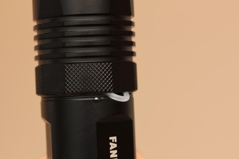
It's not obvious here, but I found out when reassembling the light that the O-Ring diameter is too large for the light.

Here's what happened the first time I tried to reassemble the light. Fortunately I noticed before severing it completely. getting the O-Ring to go in properly requires a series of small turns each followed by pushing the O-Ring back into the groove. Once it goes far enough, the O-ring stays in place and everything is fine from there. I find this to be a let-down, and not sure how this could have been unintentionally overlooked during manufacture. On the bright side, once the light is assembled, it does still appear to be waterproof at that joint.

The threads are well cut, very smooth, trapezoidal, and were adequately lubed. They are nicely anodized, allowing for tailcap lockout.

Tearing this light down was met with limited success. The tailcap is glued, so at this point I cannot get in there and assess the spring quality (although visually it looks fine) and make a spring mod. There is enough compression to allow a protected 26650 (TF Flame) to barely fit without crushing anything.

Onto the head end. Opening up the head at the bezel allows access to the lens, O-ring and reflector. The teardown hits a snag here, as you will see.

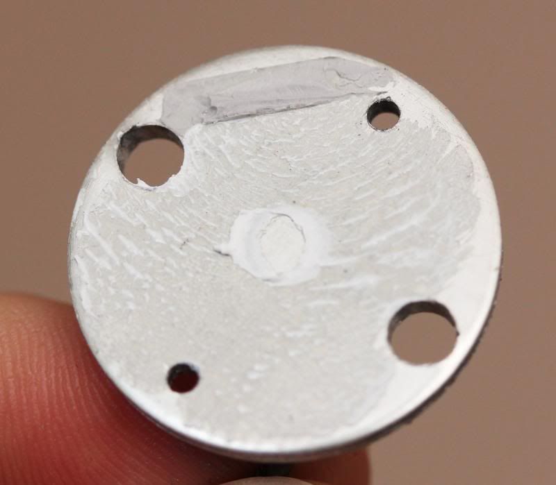
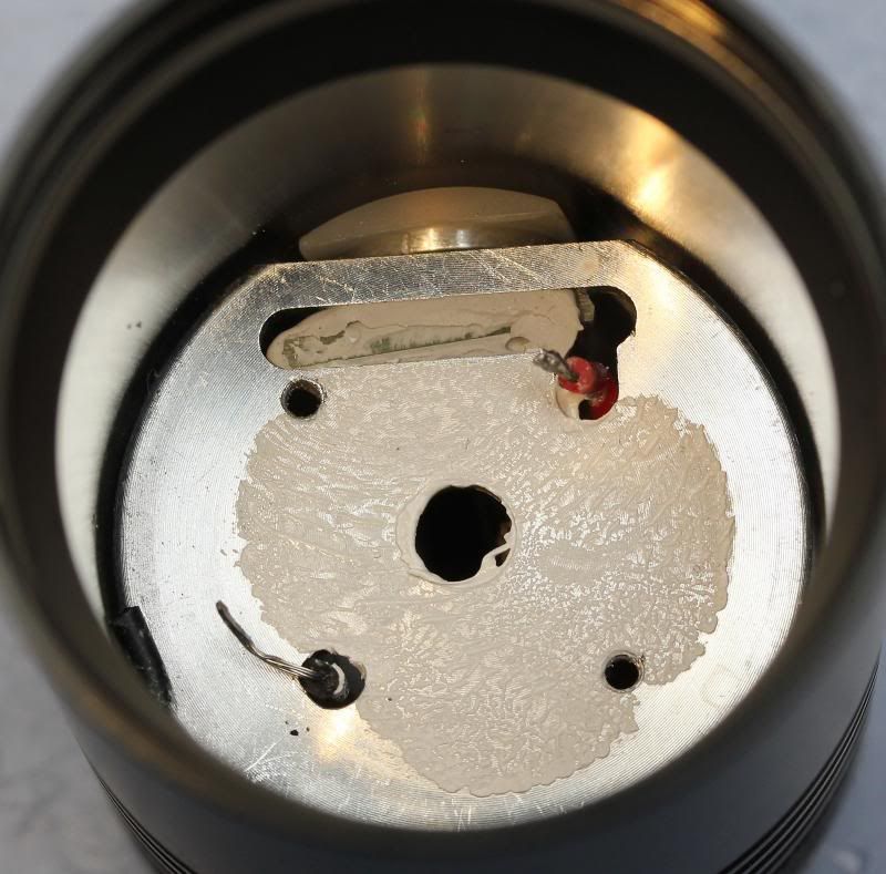
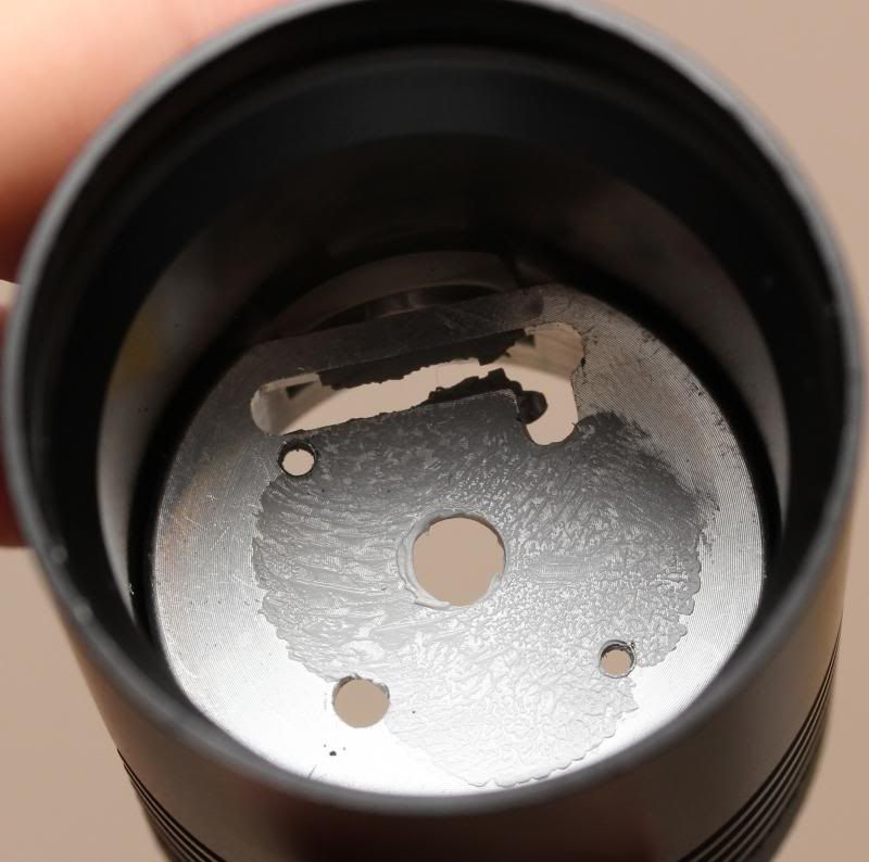
The head is made of a tube (thinner than the body) with a large pill pressed in or screwed in, I have not determined which yet. The large thick emitter plate is screwed to the pill and uses thermal paste underneath.

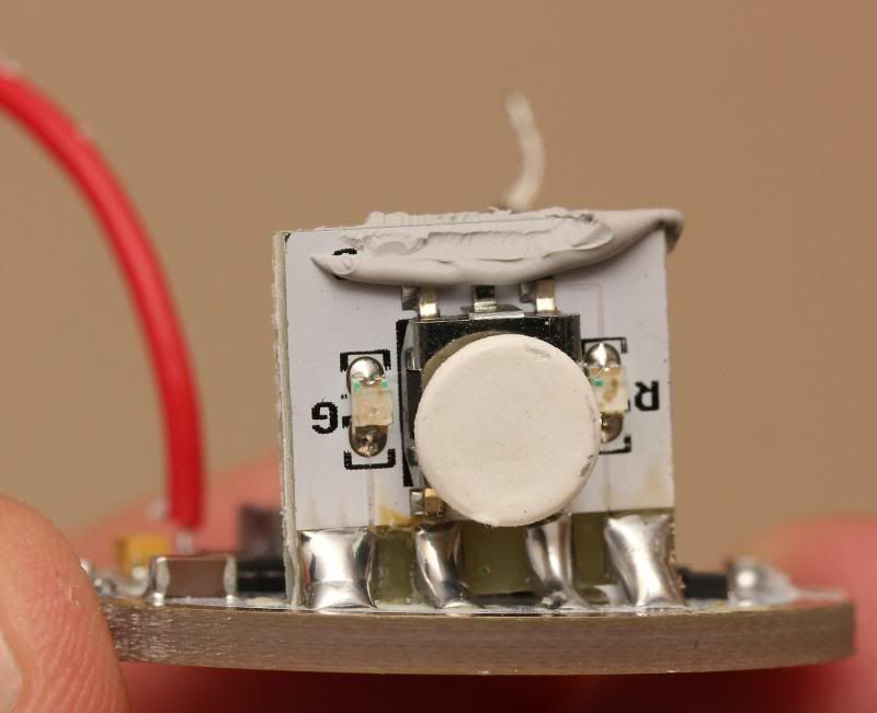
There is also some adhesive holding the switch side of the emitter plate, seen in the image below. I believe it is a potting compound or adhesive for holding the switch itself. This made it difficult to get the plate up to look underneath. When I finally did get it to move, I found out the hard way that there is no slack in the emitter wires. The positive wire snapped when the plate came loose. Underneath there is a small central hole, but the pill itself seems thermally adequate.

How well the pill is connected to the head remains to be seen, but I could not move it at all, so there's something holding it.
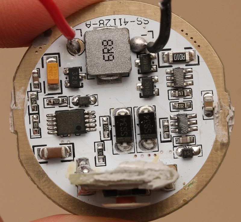
Onto the driver end it is a similar story, no entry. I could not get the driver out. I tried to push through the hole under the emitter as well. The driver remains in place... for now.

The driver appears to be a constant output type, in a buck configuration. Between 4.2V and aproximately 3.5V, the output is constant brightness with varying tailcap current. For example, at 4.2V, the tailcap current is about 2.0A. At 3.6V, the current is 2.5A. Below 3.5V tailcap current falls off as the driver enter direct drive mode (no more bucking required). This tells me that emitter current is regulated right around 2.5A (which is the spec from DX). Until I can get the driver out, it is unknown if a resistor mod is possible, but I suspect it is.
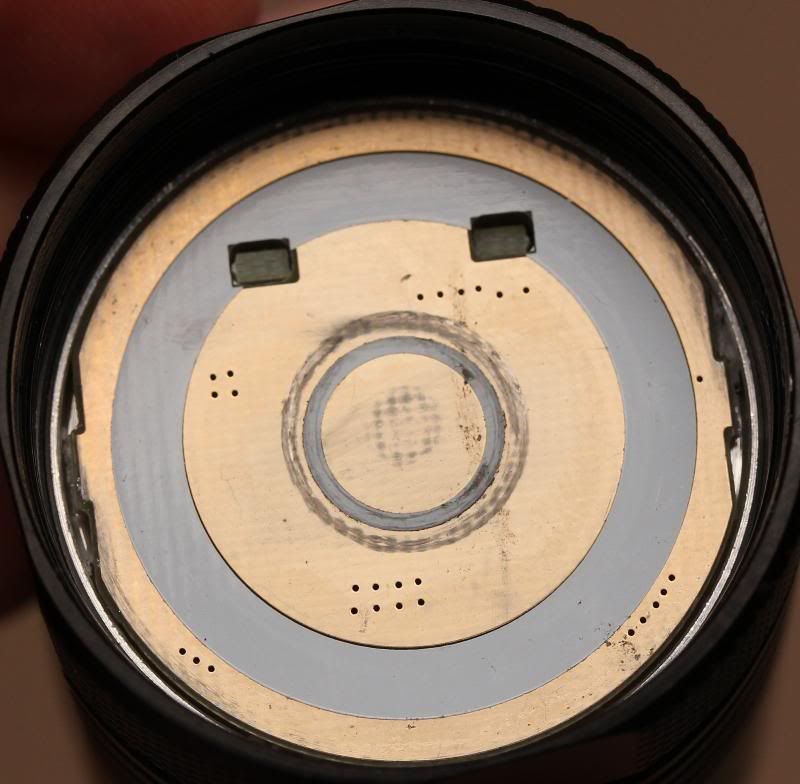
Note: Using 26650 cells in this light has produced some flickering, and I have narrowed down the cause. The inner thin white ring of silkscreen shown above on the positive contact plate is raised just enough to hold the wide 26650 positive button off of the copper plate. This is intermittent but will happen quite often. I am not sure why that silkscreen ring is there, what purpose it was supposed to serve. Using 18650 cells is not an issue due to the smaller positive contact. One solution would be to scrape off the silkscreen ring. Another would be to add a low profile solder blob to the center of the board. I'll probably go with the latter, but protected cell users may not want to add any extra height.
Packaging and Accessories
The light ships in a plain cardboard box with cutout foam for protection. All sides but the top are well protected.

Most lights I get come with a thin wrist strap I'll never use, and this one is no exception. There is an additional O-Ring as well, just as loose as the one installed.

User Interface
All modes are accessed via the single electronic side-button. The button has a nice feel with a translucent silicone boot. The cover is translucent to provide feedback tot he user in the form of green and red status LEDs. But first, the controls.
The main mode group is accessed by clicking the button. Single clicks cycle through Low - Med - High - Off.
The disco modes are accessed by holding the button for ~1.5s while the light is on. Once selected, single clicks cycle between SOS - Strobe. Unfortunately, there is no access to Off in this mode group. You must hold the button to get back to the main group to turn the light off. On the bright side, at least these modes are hidden.
Another related issue, Strobe should be easier to access, maybe through a quick double-click would be good. Right now you have to turn on the light, hold the button to change groups, then click once to move from SOS to Strobe.
Moving on to the status LEDs, which are used to indicate battery condition. These seem to have been well thought out. There is no status indication while the light is off.
While on with a battery above 3.0V, the button glows a dim green which indicates a good battery status. So dim in fact, I was not sure it was working when I first tired it. However, in dark conditions the green is a very nice level. Not overpowering or distracting, just obvious that the battery is good.
This got me thinking that the red low battery indicator would be too dim. When the battery voltage drops down to about 3.0V, the button turns a bright red. If you are looking in the general vicinity of the light, you will notice it. Once a low battery has occurred, the button will latch red while on, until the battery is removed. This is good because Li-Ion cells tend to self-rebound some voltage after the load is removed, but the cell is still depleted. the latch makes sure that you know right away the next time you turn on the light.
As the battery drops further, at around 2.7V the button stops glowing red and flickers periodically along with the main emitter. The main emitter flickering is very obvious, but the pulse is so quick you do not lose focus on your target.
Once the battery gets to about 2.5V, the light turns off. The light will allow turn on if the cell self-rebounds, but the low battery status is maintained.
Compared to:
Here's a shot of the K2 next to what I consider alternatives, the EA4 and D40A. This shot was taken later, so please excuse the quality. THe K2 is longer and about the same diameter ans the other two. I will note that on my sample, the body tube cutouts align very well with the switch position. I'm not sure if this was intentional, but it is nice. Something I never noticed on the SWM D40A until now is how the body features do not line up with any design features on the head. Mostly aesthetic, and possibly unintentional, but I like that my K2 does line up. Handling would be ever so slightly more awkward if the triangular tube cutouts were misaligned with the head.

Beamshots
Here are some white wall beamshots, 1m distance, high, med, and low. The hot spot is well defined with a typical XM-L corona. There beam is very smooth with tiny rings close to the hotspot when on a white wall within a foot or two. Definitely not noticeable during normal use.
Camera settings the same for all three; 1/20s, f/8, ISO400, Daylight.
High:

Med:

Low:

Measurements
Dimensions:
- Overall Length: 128.6mm
- Bezel/Head Diameter: 41.1mm
- Body Diameter: 37.6mm
- Tail Diameter: 39.0mm
- Reflector Inner Diameter: 33.5mm
- Reflector Outer Diameter: 37.8mm
- Reflector Depth: 27.1mm
- Reflector Emitter Hole Diameter: 7.5mm
- Lens Diameter: 38.0mm
- Lens Thickness: 1.9mm
- Emitter star diameter: ~25mm
- Emitter star thickness: ~2.0mm
- Driver diameter: ~33.6mm
- Pill inner diameter: Unknown
- Pill inner depth: Unknown
- Pill outer diameter at threads: Unknown
Weights (without batteries):
- Overall: 194g
- Head: 98g
- Body Tube/Tailcap: 96g
Performance (stock, TrustFire 26650 Unprotected, 4.1V, uncalibrated test equipment):
- Light Output: ~672 lumens at start, ~634 lumens after 30 seconds
- Beam Intensity: ~15.7kcd
Power Source Options: 1x26650 or 1x18650 unprotected or protected cell, raised positive cap. (note: possible contact issue with wide-topped 26650 cells)
Switch type: Side, electronic, with indicator LEDs
Modes: Low (0.18A), Medium (0.83A), High (2.0A), hidden SOS and Strobe
Mode Memory: None, starts in Low
Standby Current: 1.2mA, rather high. Recommend removing the battery or using the physical lockout capability when not using the light for a long period.
Conclusions
With the exception of a few issues (O-ring, battery contact, Low frequency PWM, simplistic user interface), the FandyFire K2 is a well built light. It has very good finish, an excellent reflector, and is a nice looking light. As a 1x26650 tube light, this is one of the nicer ones I've seen. As competition to the Nitecore EA4 or Sunwayman D40A, the only advantages it has is price and (for some) Li-Ion support.
As delivered, cautiously Relic Recommended, for those willing to:
- replace the O-ring,or live with it, as I will
- address the positive end battery contact issue, either with a simple mod or cell selection
As a mod host, for now it is Not Recommended. With no easy access to the driver, and difficult access to the emitter there's not much a modder can do. An emitter swap is possible, since the star could be desoldered and reflowed. With a thicker than average star, replacing it with a Direct-bonded version will present mechanical challenges.
Once it's figured out how to get the driver out, the modder status will likely change to recommended.
Thanks for reading! searchID8934