I always skip the middle pin and just solder the ground tab behind, because I find it very difficult to solder the middle one as once I accidentally touch the other pins the solder would connect the middle pin with the others and mess everything up.
I use CA to stick the chip on before soldering. The new one does not move that way ![]()
What’s “CA”?
Super glue. CyanoAcrylate.
Thin layer dries fast.
Ahh. Ok, thanks.
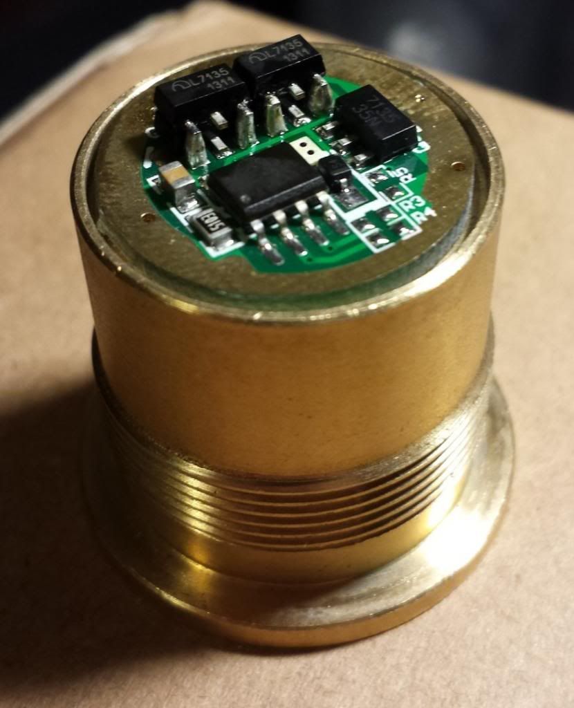
Tom E,
Which drivers are those in your pics?
Those are Nanjg's - best deal is FT for $3.05 each, in qty, cheaper. Some guys are against bending the pins, but I always do - did 100's of them. Don't use a vise though - I use a bent needle-nose and bend all 3 at once - go slowly though, and use my thumb to do the bend. Only time I've broke pins is when I hurried. They are all crowded - you need good vision, good light when doing this. I use drug store glasses (from DX maybe?), like 2.5x strength, but I need those for any close-up work anyway with how my contacts are.
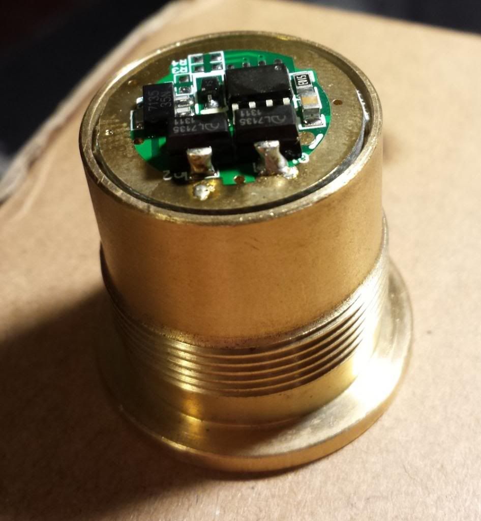
This was my first effort…
I used a drop of super glue to hold them and it worked a treat!
I'm going to do a couple of 14x7135's, 2 triples, so I'll take pics again. I got 18 Nanjg's floating around now and can easily go thru them all if I had time... At $2.68 qty 5, and the 7135's at 11 cents qty 100 (24 cents for 380's qty 10), it's really not much of an expense, so you don't have to worry so much about mistakes, but I've always been able to recover the board from bridging pins, or loosening a bottom 7135, etc.
With all of this, I was thinking (just thinking/some ideas) that it might be easier to:
- Bend 3 pins (already discussed)
- Use super-glue to hold the chips together
- Solder the 3 pins first
Assuming the 1st two above are done, the 3rd one (solder the 3 pins) is not difficult… it’s like “normal” soldering, albeit with sometimes cramped spaces. Then, once all 3 steps above, I’m thinking to put something between the unsoldered top and bottom chip tabs (not sure what yet, maybe small piece of small gauge wire, like wirewrap wire?) and then solder the tabs together, rather than just do the “glob of solder and drag and pray”.
Or, maybe “wire glue” (Wire Glue - a perfect tool for DIY flashlight modders with actual test (picture heavy) and a little tutorial - how to) would work for bridging the tabs?
Edit: Instead of super-glue, I was wondering if AA (2 part) would work? Does that melt under high-temp like the Fujik glue apparently does?
Don’t use Wire Glue. Those tabs are thermal pathways for heat transfer. I tried using a piece of wire, and copper braid. In the end, it was more of a hassle, and looked even sloppier. A nice fat soldering tip lifts the solder blob best.
I hope that I can explain this clearly… let me try: The thing that I had problem with was getting the soldering tip TO the tab on the bottom 7135. Some of the spaces were pretty tight, plus it seemed like it was really hard to angle the chisel tip to touch the tab on the bottom 7135.
I don’t know. Maybe I had the top 7135 “too far forward”, such that its tab was overhanging the tab from the bottom 7135?
Okay. You were talking about the three little legs(tabs) I thought you meant the large one on the back of the chip. I think it depends on the day. Some days everything goes great, and others, I ruin the whole damn driver. Keep trying different tips and temps til you find one that is best for lifting the solder from the bottom to the top. You can ignore the center foot since it does the same thing as the one in the back. You can snip it right off. I have stacked chips by placing a piece of pre-tinned small diameter wire against the bottom and top legs, touch your tip to it until it attaches, and snip off any excess at the top.
A piece of awg12 solid(house wire) fits nicely between the large ground tabs and makes for a better thermal path for the upper chips. 
I did wonder what that was. ![]()
That is a cool idea Rufusbduck!
I’m finding that something was said earlier on (maybe in the OP) is definitely the case… practice really does help.
I got the first one, but it was a mess. Last night, I thought I wouldn’t be trying this again, but I did earlier tonight, with the AA, which also was a mess.
Then, I just did another one, this time with no adhesive, neither Fujik nor AA, just followed the info in the OP.
I did still bend the 3 pins, but then held the chip with tweezers on top of the original 7135, and I actually used my regular pointy soldering iron tip, and I was able to get the tabs bridged (the chunky chisel tip I tried earlier made it to hard to get to the tab on the original chip).
I noticed that the top chip was slightly off to one side, so again, using the tweezers to hold the top chip, I heated the tabs, and slid the top chip over a bit, then let the solder cool, and then I checked the 3 pins and they were lined up pretty well (and touching the pins on the bottom chip. It was then easy to solder the 2 outer pins, and voila!!
I will say that this last chip, the 7135 was pretty much out in the open on the PCB, which made things a little easier, both for the tab and the pins.
I have 3 7135s on top of the original 8 now, but am measuring 3.65 amps (chips are 380 mA 7135s), so I think that the battery is now my limiting factor. I ordered a couple of PDs last night from FT, so it’ll be interesting to see the tailcap current looks when I try them. I’m hoping for ~4.1 - ~4.2 amps :)!!
Did you measure the current before adding the chips? The reason I ask is undersized leads will lower measured current dramatically. So will any weak contact points elsewhere in the set up. I now use awg 12 stranded taken from an old heavy power cord.
While testing 12x7135 (350mA) for 4.2A, wirings and switch resistances can really affect how much current you can get. My latest reading is 3.95A.
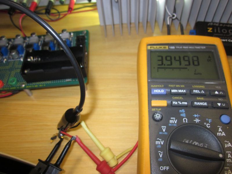
For the above, I have bypassed the switch. Need to improve my test setup!
![]()
On my setup above, you’re right! Currently my wirings really need to be improved. But having a good setup and readings will only show you the best scenario! Like having a good power source that do not sag and big wirings. Different when using a battery and on the flashlight. ![]()