Don’t use Wire Glue. Those tabs are thermal pathways for heat transfer. I tried using a piece of wire, and copper braid. In the end, it was more of a hassle, and looked even sloppier. A nice fat soldering tip lifts the solder blob best.
I hope that I can explain this clearly… let me try: The thing that I had problem with was getting the soldering tip TO the tab on the bottom 7135. Some of the spaces were pretty tight, plus it seemed like it was really hard to angle the chisel tip to touch the tab on the bottom 7135.
I don’t know. Maybe I had the top 7135 “too far forward”, such that its tab was overhanging the tab from the bottom 7135?
Okay. You were talking about the three little legs(tabs) I thought you meant the large one on the back of the chip. I think it depends on the day. Some days everything goes great, and others, I ruin the whole damn driver. Keep trying different tips and temps til you find one that is best for lifting the solder from the bottom to the top. You can ignore the center foot since it does the same thing as the one in the back. You can snip it right off. I have stacked chips by placing a piece of pre-tinned small diameter wire against the bottom and top legs, touch your tip to it until it attaches, and snip off any excess at the top.
A piece of awg12 solid(house wire) fits nicely between the large ground tabs and makes for a better thermal path for the upper chips. 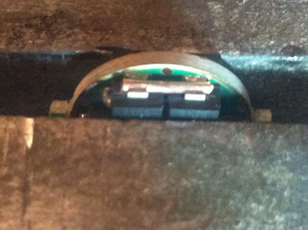
I did wonder what that was. ![]()
That is a cool idea Rufusbduck!
I’m finding that something was said earlier on (maybe in the OP) is definitely the case… practice really does help.
I got the first one, but it was a mess. Last night, I thought I wouldn’t be trying this again, but I did earlier tonight, with the AA, which also was a mess.
Then, I just did another one, this time with no adhesive, neither Fujik nor AA, just followed the info in the OP.
I did still bend the 3 pins, but then held the chip with tweezers on top of the original 7135, and I actually used my regular pointy soldering iron tip, and I was able to get the tabs bridged (the chunky chisel tip I tried earlier made it to hard to get to the tab on the original chip).
I noticed that the top chip was slightly off to one side, so again, using the tweezers to hold the top chip, I heated the tabs, and slid the top chip over a bit, then let the solder cool, and then I checked the 3 pins and they were lined up pretty well (and touching the pins on the bottom chip. It was then easy to solder the 2 outer pins, and voila!!
I will say that this last chip, the 7135 was pretty much out in the open on the PCB, which made things a little easier, both for the tab and the pins.
I have 3 7135s on top of the original 8 now, but am measuring 3.65 amps (chips are 380 mA 7135s), so I think that the battery is now my limiting factor. I ordered a couple of PDs last night from FT, so it’ll be interesting to see the tailcap current looks when I try them. I’m hoping for ~4.1 - ~4.2 amps :)!!
Did you measure the current before adding the chips? The reason I ask is undersized leads will lower measured current dramatically. So will any weak contact points elsewhere in the set up. I now use awg 12 stranded taken from an old heavy power cord.
While testing 12x7135 (350mA) for 4.2A, wirings and switch resistances can really affect how much current you can get. My latest reading is 3.95A.
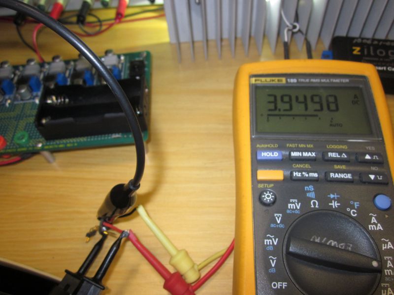
For the above, I have bypassed the switch. Need to improve my test setup!
![]()
On my setup above, you’re right! Currently my wirings really need to be improved. But having a good setup and readings will only show you the best scenario! Like having a good power source that do not sag and big wirings. Different when using a battery and on the flashlight. ![]()
It won’t help in the flashlight but will tell you when you have modded a board correctly so you’re not guessing. The last boards I modded I couldn’t get the current I was supposed to until I took the switch out of the circuit and then it was spot on 10 x 380mA. I have a new 10A switch to install but at least I knew there wasn’t a problem with my soldering.
I agree Rufus. ![]()
I measured 4.5A  last night in a XinTD C8 v4 with 12 380's (4.56A) on 3 different cells: SONY 30A, Samsung INR 20R, and Samsung INR 15M. The 15M was pulled from a power pack. The XinTD has a XM-L2 U2 1A de-domed on a Noctigon, screwed down with AS5, lapped surfaces, 22 gauge wires cut to min size, copper braided springs, all contact surfaces treated, copper heat sink added to inside of pill. I'm now convinced I can probably achieve higher than 4.5A on a single cell XM-L2 Nanjg based driver, so plan is to attempt that. I'm amazed it held the 4.5A for quite some time, nothing formally measured, and lumens measurements showed not much loss in 30 secs.
Rufus - I've never seen a switch be a limiting factor on amps, always seems to be the spring, even on that cheap, small switch in a XinTD X3. It's easy for me to compare in a lightbox - put the light in assembled, test it. Then right in the lightbox, remove the tailcap, heavy wire to jump the cell to the housing, and compare. When I see a loss, I copper braid the spring, solder the spring up if it's lacking, and it recovers all or 90%+ of the loss every time. Not sure if this is a 100% legit test though, because even the heavy wire with a simple touch contact is not ideal, so there may be more lumens/amps to gain I can't measure so easily.
Pana PD's are good with their capacity, but nowhere near the ability of a SONY 30A, Samsung 20Q, or Samsung 20R in achieving top high amps. I'd recommend at least a pair of 20Q's or SONY's to try if you are doing a FT order.
Rufus - +1 on the copper wire in the ground tabs -- gotta try that one!
That's brilliant! Thanks for that tip!
-Garry
BTW Rufus, do you glue the 7135s down when you do that? Otherwise, how do you place the chips with the wire, and keep stuff in place while you’re soldering?
I missed the “remove the spring” and add the “inverse” spring part, so I’ve only been able to get to the 7135s on the top side (the side with the emitter leads), because I have one of the 20mm partition boards with the hole soldered onto the original spring.
I still say that both Fujik and AA seem to melt and the 7135 moves around when trying to solder the 7135 tabs though?
You can get them on Amazon or Ebay.
EDIT:
Well, since I always use bent pins, simple, easy pressure from a tweezers is enough to keep the 7135 in place - much easier with bent pins I guess. Absolutely the Hakko 888 improved my soldering "skills" as well. In fact when I accidentally cut the cord to the iron a few weeks ago, I tried with my old crap Weller, but within 5 minutes, ordered another Hakko 888! I use just the stock, small wedge tip to do the 7135's with.
I may just try it next time without bending the pins, as relic38 says, the bending may cause internal damage, but certainly the soldering would be more difficult. Have to pre-tin the legs though.
Sorry - deleting duplicate post.
I got some 14AWG wire from HD, and I tried a variant of Rufusbduck’s idea. Instead of laying the wire across the 7135 tab, I soldered the end of a piece of wire to the bottom 7135, then used a flush cutter to cut the wire to the height of the 7135 (careful! That wire will FLY when it’s cut):
I lined the 3 pins up (pins on 7135 were bent, fluxed, and tinned):
Soldered the tab from top 7135 to the end of the 14AWG wire:
Then soldered the 2 outer pins:
It’s a little more work, but at least for me, it took the “guesswork” out of stacking the 7135. I don’t know if this could be used to stack more than 1 on top though…