I’m finding that something was said earlier on (maybe in the OP) is definitely the case… practice really does help.
I got the first one, but it was a mess. Last night, I thought I wouldn’t be trying this again, but I did earlier tonight, with the AA, which also was a mess.
Then, I just did another one, this time with no adhesive, neither Fujik nor AA, just followed the info in the OP.
I did still bend the 3 pins, but then held the chip with tweezers on top of the original 7135, and I actually used my regular pointy soldering iron tip, and I was able to get the tabs bridged (the chunky chisel tip I tried earlier made it to hard to get to the tab on the original chip).
I noticed that the top chip was slightly off to one side, so again, using the tweezers to hold the top chip, I heated the tabs, and slid the top chip over a bit, then let the solder cool, and then I checked the 3 pins and they were lined up pretty well (and touching the pins on the bottom chip. It was then easy to solder the 2 outer pins, and voila!!
I will say that this last chip, the 7135 was pretty much out in the open on the PCB, which made things a little easier, both for the tab and the pins.
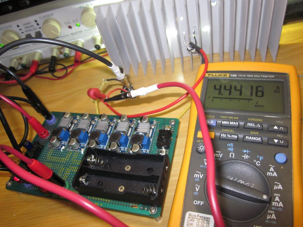
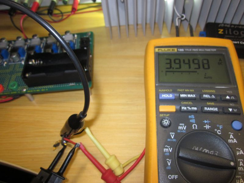
I have 3 7135s on top of the original 8 now, but am measuring 3.65 amps (chips are 380 mA 7135s), so I think that the battery is now my limiting factor. I ordered a couple of PDs last night from FT, so it’ll be interesting to see the tailcap current looks when I try them. I’m hoping for ~4.1 - ~4.2 amps :)!!
 last night in a XinTD C8 v4 with 12 380's (4.56A) on 3 different cells: SONY 30A, Samsung INR 20R, and Samsung INR 15M. The 15M was pulled from a power pack. The XinTD has a XM-L2 U2 1A de-domed on a Noctigon, screwed down with AS5, lapped surfaces, 22 gauge wires cut to min size, copper braided springs, all contact surfaces treated, copper heat sink added to inside of pill. I'm now convinced I can probably achieve higher than 4.5A on a single cell XM-L2 Nanjg based driver, so plan is to attempt that. I'm amazed it held the 4.5A for quite some time, nothing formally measured, and lumens measurements showed not much loss in 30 secs.