What a fantastic crazy mod. That electrical work is incredible and well done on getting it all to work. It must make enough heat to warm an oven.
Thanks, certainly warms up quick now! ![]() I may do a thermal runtime test to see when or if it stabilizes but it certainly hits 55+ deg C fairly fast even with these saggy batteries. Outside I’d be confident to run it on high for the life of the batteries. Nothing has melted yet…
I may do a thermal runtime test to see when or if it stabilizes but it certainly hits 55+ deg C fairly fast even with these saggy batteries. Outside I’d be confident to run it on high for the life of the batteries. Nothing has melted yet…![]()
Anyway you do some incredible work! I’m especially intrigued by your recent mt-g2 host and testing of the 5/9A ios drivers. Was planning on using one of the 9A versions to do a triple MT-G2 BTU shocker next but not sure now after your overheating experiences. Do you think enough heatsinking would keep it running more stably or is it just outspecced and too inefficient?
Cheers
This may save you some grief. This is a PM from 18sixfifty and I’m sure he wont mind me copying it here.
I tried three different drivers all together. The DRY and two from IO the 7 led one and the “up to three” one. All three worked fine for a while and then froze up and locked in place. You could turn them off for a while and they would work the IO ones anyway the DRY driver just froze and stayed that way. The two IO ones both ended up crispy critters and totally non functional. None of them lasted long enough to be worth trying again.
I too was going to build a triple MTG-2 with some help but have put it on hold until something comes up that will drive it. If you find anything let us know. Cheers.
Oh well damn, that doesn’t sound promising. I have one on the way anyways so I’ll approach it with caution now that I know they fail and maybe I can figure out which component gives out and why.
Thanks for the heads up!
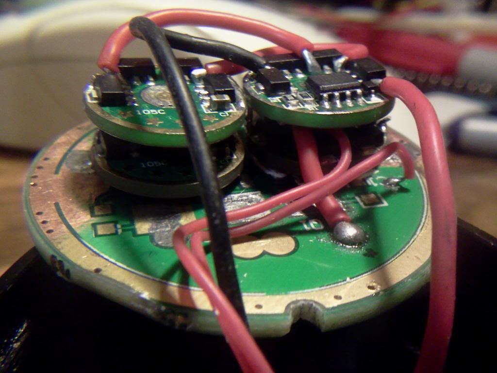
Great build! That driver/spiderweb thingy is awesome! ![]() You are an inspiration to us all (or me, at the very least)!
You are an inspiration to us all (or me, at the very least)! ![]()
I have been thinking about doing something similar to my SRK….man, now that you’ve planted the idea it is going to be hard to get it out. Been reading Dr. Jones’ site about some of the 7135 driver possibilities and it seems doable, even with the electronic switch.
Wow! What an amazing job, Linus!
Cheers guys.
Hah, I’m beginning to think there’s not much you can’t do with those little 7135 fellas. ![]() The fact that they are just as happy driving mt-g2s as in your build has really got me rethinking my BTU triple MT-g2 build now!
The fact that they are just as happy driving mt-g2s as in your build has really got me rethinking my BTU triple MT-g2 build now!
Especially since the current driver options for this configuration on 3s seem to be going up in smoke! ![]()
Thinking out loud right now but how does this sound to the experts on here…
BTU Shocker host with 3x MT-G2s on noctigons wired in parallel.
-Some heatsink improvements if possible i.e Thermal Path from the LED mounting plate to that massive reflector… maybe over a copper gasket that fits between the noctigons?
Beefy external belt Lipo 2S power pack
-Thinking about building this from an Otterbox 2000/3000
-Lots of capacity and won’t sag much under high drain. Plus I have loads of lipo cells I can salvage from my RC helis.
-Loads of room inside the body if I don’t have to/want to run it on 18650s. As an alternative it may even be possible to find a bigger 12v LED buck/boost driver that fits into the body of the light.
-I’m a big fan of handles on bulky lights so maybe add one to the BTU and find a way of integrating a thumb clicky switch.
-Drivers based on 7135s with MCU modded for >6v, maybe 3 in parallel stacked to high heaven! ![]() Total output on high around the 15A maybe.
Total output on high around the 15A maybe.
-That should get it close to being a 100W light…right? ![]() …Toasty!
…Toasty!
-Maybe run it with 4 modes on a custom programmed mcu to get 5A per emitter on Turbo, 3A each on High and then sensible and usable Mid and Low
-I suspect I will need to figure out very good heatsinking for the drivers to stop it all melting, no idea how hot these would get running at over 6v @ 15A and dissipating the voltage excess of fully charged 2S lipos (8.4v). Need to study those great Mt-g2 emitter tests on here again! Has anyone done tests on the 7135 drivers to see if they get much hotter/less efficient/quirkier running at 6v vs 3v?
It’s so much fun coming up with crazy, silly torches like this! hehe
Linus
RMM wrote:
Great build! That driver/spiderweb thingy is awesome!
You are an inspiration to us all (or me, at the very least)!

+1. Well done.
Linus, your ideas sound feasible. The packaging would be tricky, but you’ve already shown that you are more than capable of pulling it off.
In regards to heat; my understanding is that the 7135 chips basically burn off excess voltage in order to reach the constant current. Given V=I*R, Watts=I*V, it is the difference between the input voltage and LED vf needed to meet the given 7135 current output that is burned off as heat. So…the less the batteries experience voltage sag the more heat will be put into the chips. More heat will be put into the chips at higher mode levels (higher duty cycle) than at lower modes, because when the 7135 is switched off it isn’t producing heat. It is possible that the 7135s are running hotter at 6v than at 3v but I’m not sure by how much, would need to get some measurements to know for sure. Despite all of this speculation, however, we know that the 7135s can survive driving a 6V MT-G2 so it should be possible to do what you want to do.
In my light the 105c is pressed into the pill and has a decent thermal path, at least from the pcb to the pill, so it is getting some cooling, even though the 7135s do not have a direct thermal path. Like you suggested, you may have to figure out some way to transfer some heat from the drivers into the reflector or body. 5 amps/board is definitely possible.
Glad to hear I’m not complete barking up the wrong tree here, will be giving this a go as soon as the parts arrive.
What’s the general consensus on here about flashlights that use external power packs for big lumen output, is it considered cheating? ![]()
On the 7135s that’s a very clear way of explaining how they work and confirms what I’ve been seeing in terms of heat dissipation and efficiency. Will be interesting to see how they handle what i’ve got planned. I suspect I’ll have to stack them vertically inside a heatsink tube or brass pill that can suck the heat off directly. Actually I’m excited I can do something else with these drivers, still have 40 of the little 0.380A fellas in a drawer and they need a home. ![]()
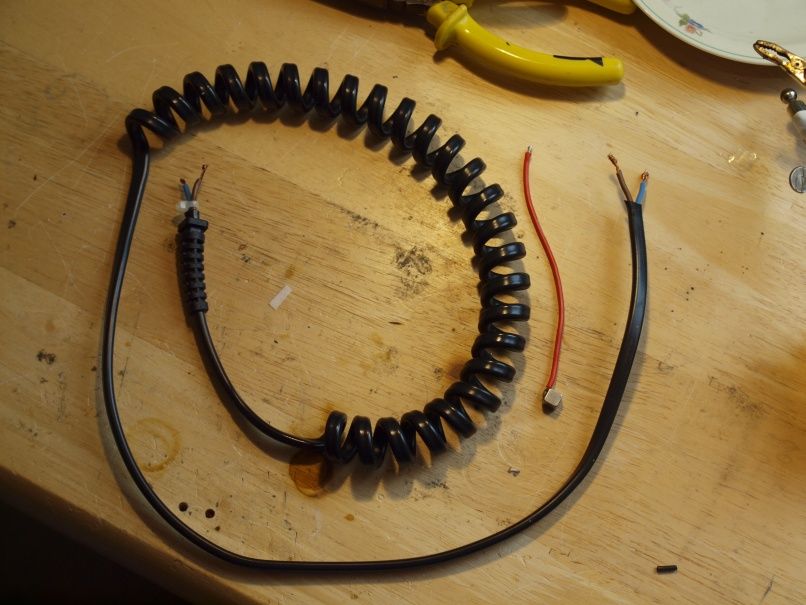
Today I was playing around with making a flexi-cord from various power cords I had lying around. Trying out various thicknesses and materials. Ultimately I want to have a spiral wound flexi-cord to connect the flashlight to the lipo pack and at 15Amps it needs to be pretty substantial to not suck up all my precious volts before they even get to the regulators!
Made them all “spirally” by winding tightly around a dowel and heating them as much as I dared with a heat gun then let cool. Works ok and they stay wound, but the materials found here are not quite as keen to return to their fully wound state as I’d like.
I found that even for a relatively short reach of around 45cm (in it’s semi wound state, quite a lot longer unwound) the resistance losses really add up quickly. My best result of the day was with a shaver power cord that has what looks like 18awg copper core wires inside. Best result, as in it didn’t weigh half a tonne because of excess plastic coating (white cable) or heat really quickly and drop almost 1.7v under the test load (thinner black cable). That said it still dropped just over 0.8v on my test rig at 15A which I hope will come down once everything is soldered tight and the excess cable trimmed. It’s certainly something I’ll need to keep an eye on as it will have a fairly big effect on the whole power setup and I don’t think I can go much thicker on the cord without making it too heavy and cumbersome. Obviously there’s no point in having a stout battery pack that doesn’t sag when you lose all the benefits getting that power to where it’s needed!
The winner
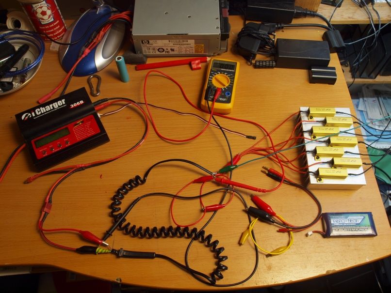
The test arena
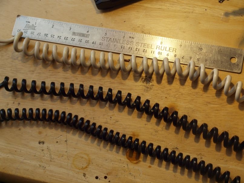
The rejects ![]()
Should probably start a new thread for the BTU planning and tinkering…
Cheers
Well you definitely got me beat.
.
.
.
Nice job LinusHofmann. I feel your pain ![]() Mine’s only running 4 amc7135 2800mah drivers. Should give 11200ma, but only does a little over 10amps in a 4-xm-l kung using Panasonic 2900’s laptop pulls. Really didn’t take as long as I had thought it would to throw these boards together. Thanks for sharing and great mod.
Mine’s only running 4 amc7135 2800mah drivers. Should give 11200ma, but only does a little over 10amps in a 4-xm-l kung using Panasonic 2900’s laptop pulls. Really didn’t take as long as I had thought it would to throw these boards together. Thanks for sharing and great mod.
Oh cool, and that’s running the electronic switch similar to the SRK right? I assume you had to flash some custom firmware to get it to work right with these drivers. I should probably read up on how all that electronic switch stuff works, could come in handy for sure!
007, please share the juicy details of your setup. ![]()
Great mod and work!
Sounds like you made an awesome light.
:beer:
There’s a little more detail in this thread.
Great build. Of course, we still need beam shots.
Working on it ![]()
OK so today I received 3 more of the Kinoko IMR 18650s from IlluminationSupply and I thought I’d do a quick runtime test on the Apex to see just how toasty it gets when driven by some stout IMR cells.
I was also keen to see if my driver heatsinking would be adequate over an extended period on full or if I would see some throttling back of the current from the 7135 chips as they get too hot.
Incidentally the Kinoko cells have an internal resistance of between 85-95milliOhm which seems pretty good to me, in comparison my year old Protected Senybors (2400mah) are up around 155-170 each and the Protected Trustfire Flames that I’ve tested are also in that range. Tested on my iCharger306B with relatively long and sloppy leads so take them only as comparative figures.
So anyway here are the results.
–4 freshly charged Kinoko IMRs reading 4.22v each
-Run on high with IR temperature readings taken at the head every minute.
-No fan or air movement of any kind, flashlight lying on it’s side (didn’t want to risk burning a hole through my desk :P)
-Tailcap current readings taken with my trusty Turnigy Wattmeter with 12Awg leads soldered directly to the switch tab solder points (see above for a picture of the test setup)
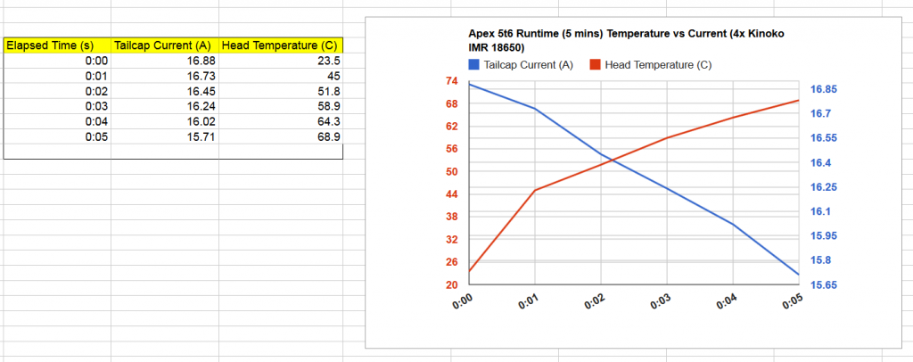
I called it a day at 5mins because with temps still rising steadily and close to 70C at the head I started to get a little nervous! Didn’t want a runaway meltdown scenario! ![]()
That said the temperature reading of the body was obviously at a lower level, inside the battery compartment taken from the driver PCB was at a safer 45C and the batteries themselves came out of the flashlight at 47.5C.
In terms of the output stability and how these batteries performed I’m really impressed.
The current readings where much more stable than I was expecting and didn’t exhibit anywhere near the sagginess of my Senybor or Trustfire Flames. Seems ~4A per cell for these IMRs is cruising speed ![]()
I also don’t think the steady drop in current as seen has anything to do with 7135 chips overheating and throttling back so that’s reassuring. It all looks to me like solid battery performance with an expected gradual drop.
Conclusion is this light loves IMR cells, and can safely(ish) be run on high for <5min bursts. Again outside at night with cooler ambient it’s a different story and should stabilize at a lower temperature. Plus the handle makes holding the light at high temperatures fine although it’s easy to forget and accidentally touch the head with your index finger for a nasty surprise!
Thoughts welcome but I think I’ve achieved the aim of making both a camping light and heating stove all in one! ![]()
Hopefully I can get some beam shot comparisons done tonight.
Linus
Thanks for the graphs. Looks like those cells experience very little sag.
I didn't even know there was a Rules Committee. 
That's great work.