Flo, that is an interesting one. Not super long, but still a huge light. Gotta wonder about the heatsinking internals, will it be better than the AK90? I’m still wondering that about the J20 as well.
I will be getting this light next. I do have an extra hyperboost driver just sitting on my shelf! Im kinda wondering how fast I can get it from kaidomain though.
Ken
that shorty is pretty sick. but its prolly not as bright as the longer version
When I get that shorty 12xXML light, I should be able to turn up the hyperboost driver to 2.6A per die with (6) 18650 batteries. ![]()
My current AK-90 is at 2A per die. But those are XML2 emitters also.
Ken
yup, this j20 and the kd shorty has been on my mind as of late.
so happy and looking foward to what you have to say about the kd shorty hyprmtr….in stock form and beast driver mode
I will be ordering in in a day or 2. I will pay for the DHL shipping maybe I will see it sooner than a month!
Ken
Mine just came today; stunned to see it fit in my mailbox!
I’m pleased with Fast-Tech’s shipping speed (Ordered on the 24th and Arrived Oct. 7th).
Didn’t have too much time to play with it; however, the following will be a brief preview and comparison.
Pictures:

Left to right: X100, TR-J20, TR-J12, BTU Shocker

Breaks apart in what looks like the middle of the heatsink.

Driver is retained by a large ring.

Driver removed.

The driver clearly reads TR-0231 and has 4 mosfets with the labels scratched off.

About 53mm in diameter.
Ceiling bounce test
Notes:
- All data is quite relative. All batteries are “mostly charged.”
- The STL-V2 has a coated lens installed.
- The BTU Shocker driver blew on me, so it’s in direct drive mode.
- The X100 had all 4 batteries installed.

Trustfire TR-J12 119.00
Trustfire TR-J20 187.00
Trustfire X100 165.00
NiteCore TM11 106.00
Crelant 7G10 62.00
BlackShadow Terminator 137.00
BTU Shocker 109.00
SkyRay STL-V2 41.00
HD2010 35.00
Overall, the TR-J20 is the heaviest and best built of them all. Extremely thick aluminum. I am disappointed with the output considering the thermal dissipation this host must offer.
Let me know if you have any specific questions I can answer.
Higher lux than the Shocker and you're disappointed. What am I missing? That sounds like a good result to me.
The pill looks cavernous. Maybe big enough for 4 BTU Shocker drivers...
wow that J20 a beast. what it’s specs?
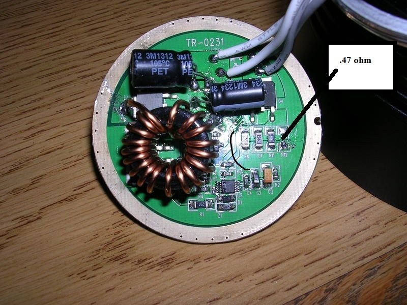
R12 slot is begging for a little resistor J)
nice.
how many mm of aluminum have this flashlight under the leds?

the surface are anodized like this?

or not anodized like this?

the heat transmission appears to be good for drive the leds at 120w some minutes ?
how many current draw without mod?
You should post more! Very helpful, thank you.
Nice light LEDMatt, I’m very tempted. I’d love to hear the answers to the questions asked above plus: did you use 32650s for the test or 26650s? Looks like the head diameter is getting closer to the shocker than the x100! How heavy is it? It almost looks like I’d have to be doing curls constantly on my 1-2hr hikes if I took that ![]()
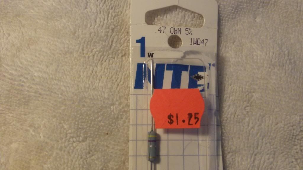
Solder in this resistor.
On the driver board here.
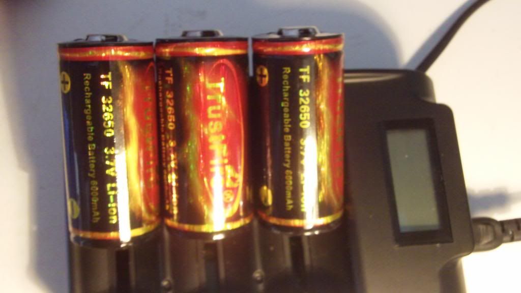
Charge up three of these.
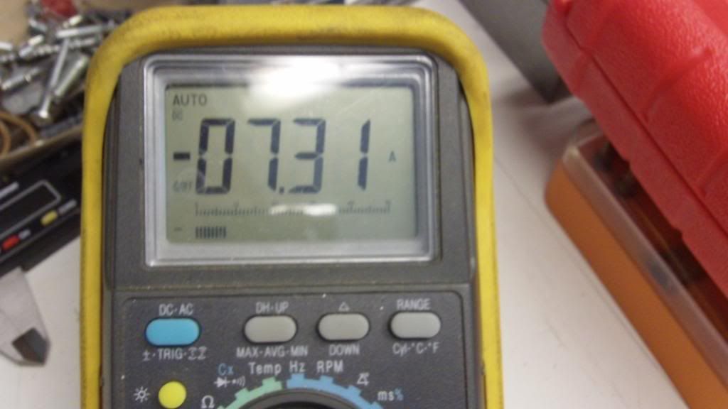
Measure the tail cap current.
The TR-j20 has two banks of six leds are driven at about 18V. So with about 7amps split between two banks you get, after losses, about 3 amps per led. Don’t know if I would want to try for any more, but It’s quite bright, sorry I don’t have beam shots, I’m too busy now, will take some in future. Good Luck, please post your results.
Here’s some answers to the questions above
- Tests done with 3x Trustfire 26650 cells
- With freshly charged cells, I read 3.18A from the tail (no mods… yet)
- This weighs 3.25LBs without cells
- Thickness under LEDs as depicted above is about 5mm
@A number 1 - Very interesting. So all I need to do is add a resister between the contacts on R12 huh? I want to experiment with this.
Tweaking this between 5 and 6 Amps is what I desire. I assume the current increases as the resister value decreases?
Any reports on runtime / duty cycles performed thus far with your mod?
It’s simple, but not THAT simple.
R12 is the missing resistor in a 4 resistor parallel circuit.
When I measured the circuit (without R12) I got about .50 ohms.
When I used the 26650’s I too got about 3.4 amps tail cap current.
So the .47 ohm resistor just about cuts the circuit resistance in half.
(it’s pretty hard to accurately measure less than 1 ohm, your meter’s leads are about .10 ohm.)
See this for formula to calculate the circuits NEW R value:
This allows about twice the current to flow.
When I changed the batteries to 32650’s, I now get about 7.4 amps at the tail cap.
I wouldn’t try for much more current that that. I’m not sure the other components will survive.
I didn’t need a LUX meter to see how much brighter it was now than stock, it turns night into day, on my street.
I did notice that the massive head and cooling fins dissipate heat extremely well, very little heating effect.
It’s not made to put on your keychain, but If you want to build inside the pill, there is plenty of room.
I havn’t done any long runs and runtime testing, I have to travel and will not be back for a week.
If you can do measurements - that would be interesting. Good luck.
Unfornately it is not that simple. You measure the amps at 3*4.2=12.6V withouth the sag. but it is converted to 18V and lower amps. You draw about 92W at the tail. without losses you divide this to 12 leds and get about 7.6W per led.Include some losses at the driver, say 10-15%, you get about 2/3rds of 10W. about 2 A per led.
I modified as suggested but with a 1 Ohm 1 Watt resister (which I had on hand; pulled from an LCD ballast board).
Results
Tail Current unmodified: 3.18A (estimated 40 Watts consumption)
Tail Current modified: 4.20A (estimated 52 Watts consumption)
Percent Increase: 32%
Ceiling Bounce unmodified: 187LUX
Ceiling Bounce modified: 235LUX
Percent Increase: 26%
A conservative mod with a noticeable change. I may go for more after some 32650s come in.
Coincidentally enough, I found a .47 Ohm resister on another junk board in the basement! I do have concerns with PCB heat and what would happen in low cell voltage conditions; however, I saw some other great ideas on the forum about cutting out heatsinks for the fets.
At least now it’s in more of an expected range given the size of this monster. Pleased with the results.
Thanks again for the clear instruction, A number 1. Hopefully I can find a resister value to boost it to 50% brightness / current intake.
Think it could take an increase to 3 A per LED and use a resistor with even less resistance? Seems like with a sturdy build like that light has it would be no problem at all, though you may need to keep it on medium most of the time after ![]() (of course I usually keep this type of light on medium anyways typically)
(of course I usually keep this type of light on medium anyways typically)