Suitable for SST-90 and SBT-90 LEDs, Low voltage protection (2cells only), Thermostat protection
Input Voltage: 5.5-12V (max 15V)
Step-Down (Buck) driver
Output current: 9A
Constant current
Modes: Low-Medium-High (10%-30%-100%)
PCB diameter: 24mm
Contact board diameter: 26mm
Height: 16mm
Gold plated contacts
Tinned leads
Thermal management, overheating protection 55-60C, the light will step down to low mode and flash 1 time each 5 seconds
Low voltage protection on 2 cells: at 5.5V the light will step down to low mode and start flashing 2 times each 5 seconds
Thermal pad material included
Measurements
Tested with: SST-90
Max. height: 17mm
Diameter: 24 & 26mm.
The driver has high, medium, low.
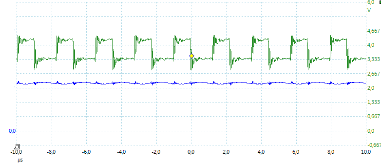
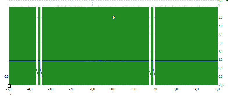
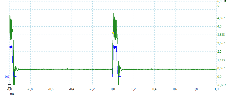
High: No pwm, only some switching noise at 450kHz.
Medium: 1kHz pwm with 28%
Low: 1kHz pwm with 3.3%
The driver has memory, the actual mode is stored when the light is off for a short time.
When turning off for changing mode, the driver is slight slow to turn on
Driver is buck only
The driver can be used with 2 or 3 LiIon batteries in series.
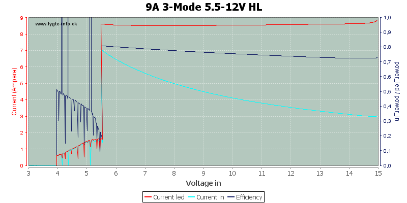
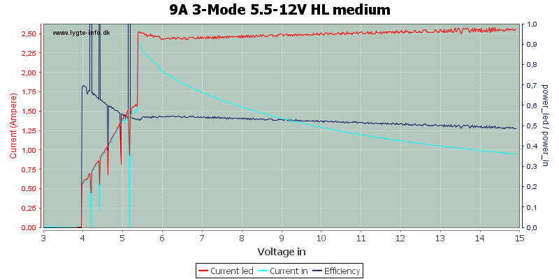
High
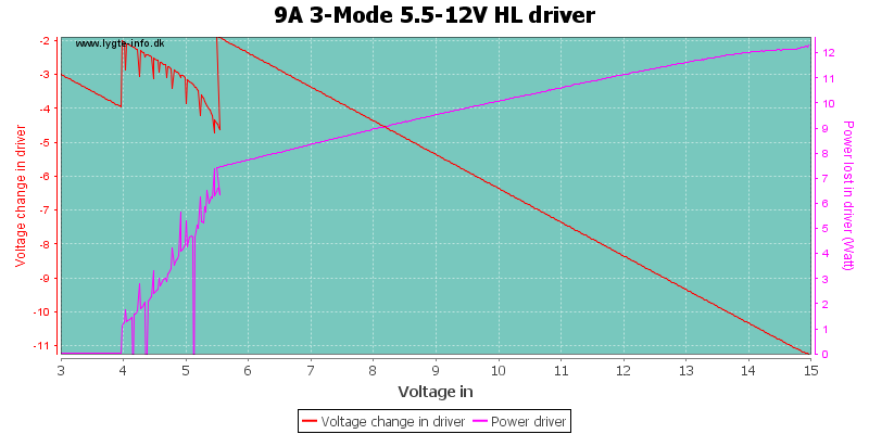
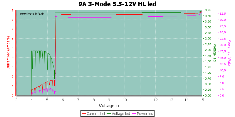
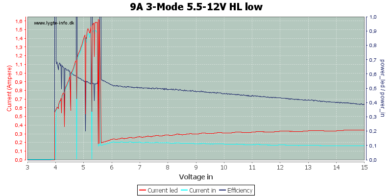
The driver keeps a nice constant output to the led, down to 5.5 volt, where the low battery warning turns on.
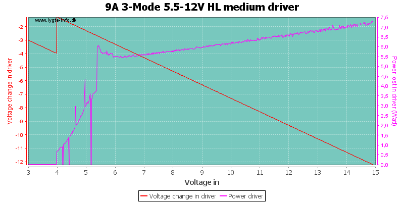
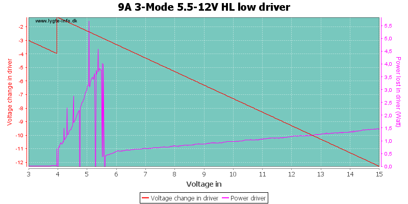
The efficiency is not that good, this means the driver needs a lot of cooling.
Up to 12 watt in the driver, it is a good detail that it has temperature warning.
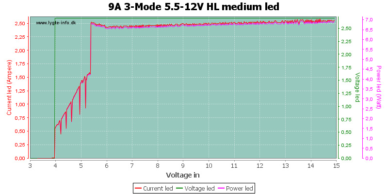
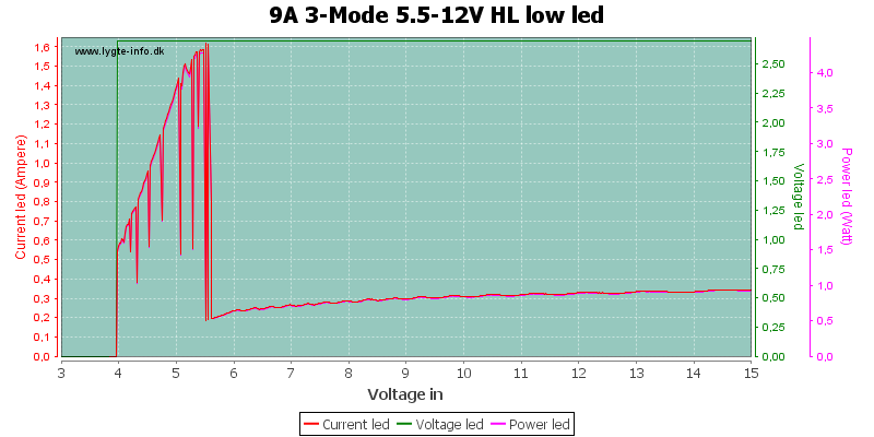
About 31 watt into the led.
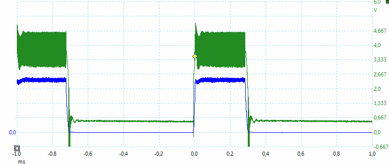
The driver is not fully filtered, some of the switching waveform reach the led, but it is at 450kHz, i.e. invisible.
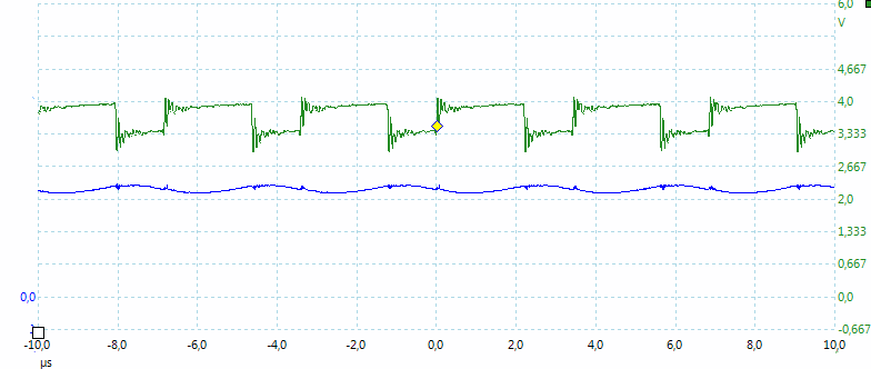
At lower voltage the switching output looks slightly different.
The low battery warning is two flashes.
Medium
Medium uses a lower current and has the same low voltage limit. The actual regulation is done with pwm.
Due to the pwm I cannot do precise voltage measurement on the led, but assumes the voltage is 3.65 volt (See led curve above).
The pwm is at about 1kHz.
Low
At low the driver has a low efficiency at high voltage (There is not much change in input current with voltage).
The pwm is at about 1kHz.
Conclusion
The driver does the job, but with only low battery warning for two batteries and the low efficiency I am not that impressed.
I would never believed efficiency was that bad on low and medium, not very impressed with high either. No wonder it has low voltage protection and that some have experienced issues with overheating..
Im not too impressed by the driver, but in some cases it may be the only high output option for its size and output..
Extremely valuable review! Looking forward to more of the driver circuits reviews! :)
Thanks!
When that is said, I don't think many people are into the SST90, so these numbers are more valuable for those wants to power up 1-3 XM-L2s. Especially one XM-L2 (if the driver is resistor modded for a bit lower output). Would you say that is correct? (that these numbers should be quite similar for an XM-L2.)
As far as I can see/guess with my limited knowledge, efficiency would probably be much better in combination with an MT-G2, especially on low and medium. Any thoughts?
btw, looks like intl-outdoor have stopped selling this driver now..
This driver looks like it is easy to adjust output current on and it will probably increase the efficiency significantly if the current is reduced.
I do not know how it will handle a MT-G2, due to the higher voltage, but 3 x XM-L2 in parallel would work.
I do not hope to many of the drivers I test, goes out of production, before I publish the review. Doing reviews takes time, also because I do not want to publish a lot of "same product type" reviews, just after each other. I prefer to mix the review types a bit.
Several people have used it with MT-G2. Some reports of overheating issues..
Current can easily be decreased (removing resistors like HKJ said), which probably makes it into one of the most compact 6,5A drivers for say an XM-L2 with the right resistor value.
Its also one of the few drivers that can output 3x3amps to XM-Ls from 2 cells in series without any driver modifications. And that is without any blinky modes, with decent mode spacing and with low voltage protection.
It may not be the best, but I think it deserves to be sold..
The driver (or basically the same driver) can be bought from LCK-LED, but its slightly more expensive than what intl-outdoor sold it for.
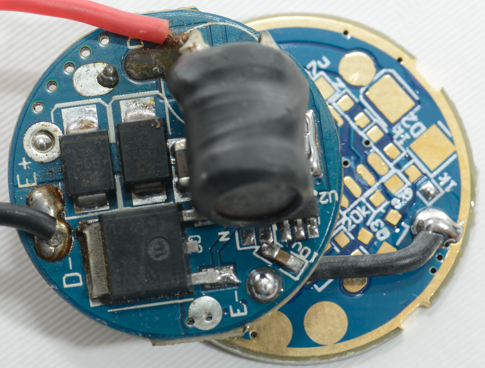
I have two of these, supposed to be the same, but one does 9A and the other only did 6.5A. The 9A one came with nine resistors - 3 on one side, and 6 on the other, double stacked. The 6.5A one only has 3 and 3.
(I changed the inductor-thing on the one on the left for space reasons, it didn't affect the output)
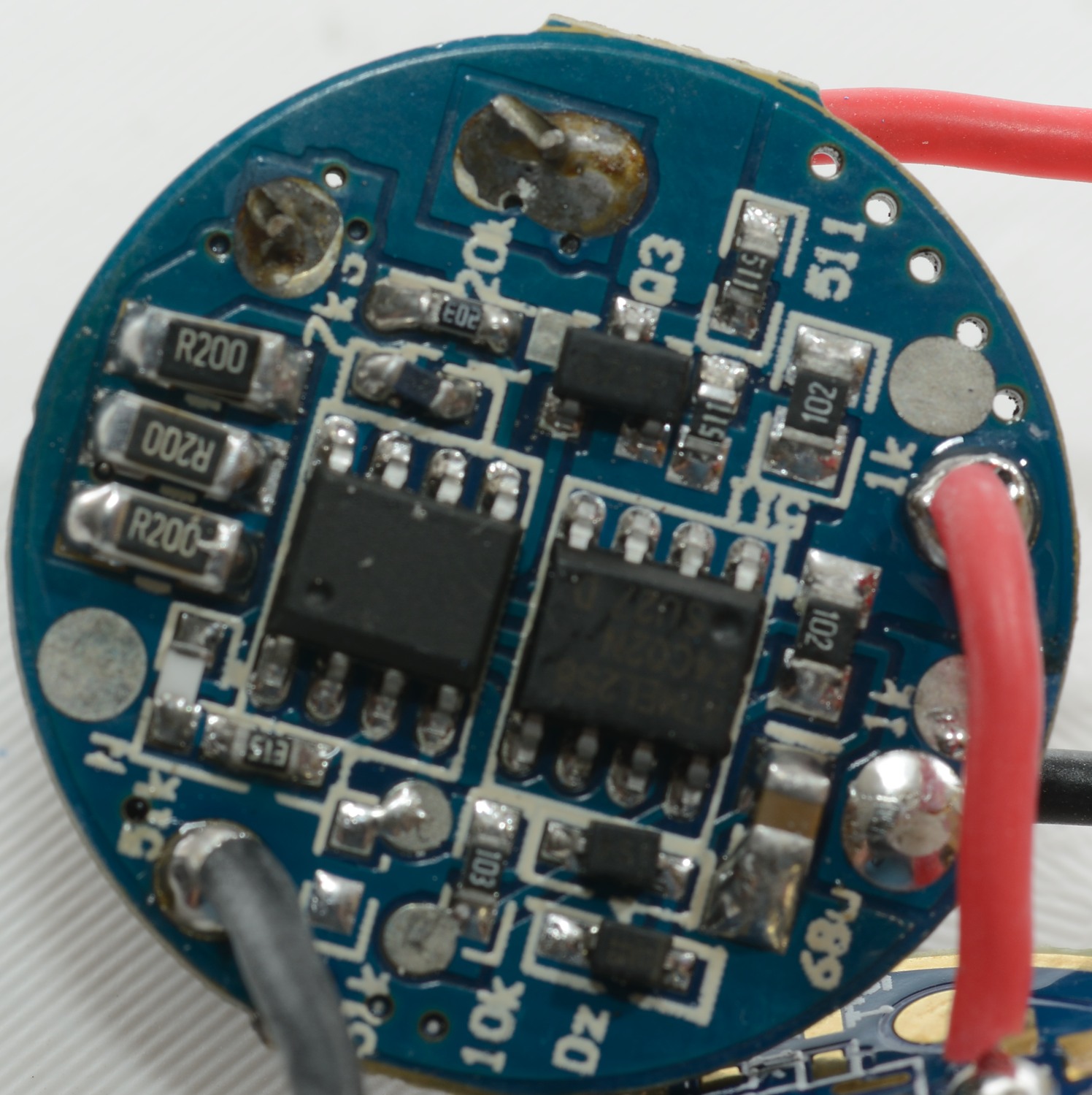
Yes, nine R200. I was wondering if the chip 5241a has been changed somehow. It should have 0.2V sense voltage. I = 0.2/R where R is 0.03333Ohm (9 times R200 in parallel). With 6 resistors R200 you would get 6A. I’ve seen 5241 chip in quite some bicycle lights including famous Magicshine.
So anyone who wants to mod it’s current can simply calculate it from the formula above.
That is not the point. When taking thermal images, I would not have the same cooling as when mounted in a flashlight, i.e. the temperature will not be the same. That is the reason I call the temperature meaningless.
You have to know a bit about what you are measuring on and how it is used, when using the result from a thermal imager.