Thanks Moderator007. Sounds like a promising candidate. One of the SRK driver variants out there uses N channel FETs too. So maybe that FET is similar to what is used in most drivers.
Speaking of FET's. The ones in the first picture of the OP were poorly seated. Probably connected good enough though.
Looking at a SRK driver (version with a large capacitor and one inductor coil). It has two N channel FET's, but I can't tell if they are wired parallel. My labels are ground off, but GTamazing has one too and his is labeled as follows:
DTU
06N03
DD13U
I think the one I have reads over 6 amps at the tail.
Well, I'm not having much luck finding .68 ohm or .82 ohm 0805 resistors around here. I even tried ebay us sellers. Nothing unless I want to go to a kit for big bucks. I don't have anything at home except for a couple R200 here, which won't help and I don't even know for sure if it will do what I want. I'm about to just use five of the NANJG drivers and call it a day, with a shortened tube and one of the Sony 50amp 26650 batteries. 15+ amps, that ought to fry eggs in a few seconds, in that light.
I just don't want to order from China. I've got a hundred bucks worth of orders already aiming for 45 days from, several sellers and nothing can be tracked and none of them want to refund, so I will have to go the paypal route soon, so no more orders from China.
Right now you are at .34ohms resistance. If that gets you to 2 amps, the voltage differential is about .68. So adding a R200 will get your resistance down to .126 and your current to the emitters up to 5.4 amps.
Do you know the size of your R200 resistors? If they are 0805's, they can only handle 1/10th of a watt and would not probably be able to be used in place of the other resistors.
EDIT: If you want to be safer, you can first remove the 2 R820's. Then you would be at about .18 ohms resistance and 3.75 amps current. The best way for me to remove a resistor is to use a blob of solder that touches both ends of the resister. It usually lifts off with the soldering iron.
Did you look at Digikey?
http://www.digikey.com/product-search/en?pv1=1333&pv1=1334&FV=fff40001%2Cfff800e9%2C4032b%2C40535%2C40536%2C40544%2C406c6%2C142c040d&k=805+resistor&mnonly=0&newproducts=0&ColumnSort=0&page=1&quantity=0&ptm=0&fid=0&pageSize=25
So what are the others on the driver? I thought they were 0805s? Guess I will have to measure.
EDIT: Looks like they are 1206, not 0805.
I can't tell without measuring, but the 3 resistors share the current. So each gets 1/3 of the total current going through them. They should be bigger because 1.36 watts (.68 volts x 2 amps) is going through that bank (if driver is delivering 2 amps stock).
0805 sized resistors measure 2mm by 1.25mm.
There are apparently 1/4W and 1/2W 1206 resistors. Which to buy?
EDIT: I just ordered a couple of both from Digikey.
If you have a couple of R200 and want a higher value.. Set them in series..(not stacked directly on top of each other/parallel)
2x R200 in series = R400 Build a pyramid on top of another resistor (you might want to remove one of the stock resistors then).
3xR200 in series = R600 Build a house (with a flat roof) with three resistors
I hope you get the picture...
another idea is put 3 or 4 R200 resistors in series in a piece of strip board and solder tiny wires from it.
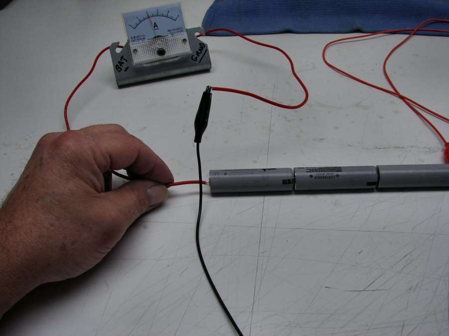
So I set up my back woods Test Facility, to test out the driver input and output. As is, before any changes.
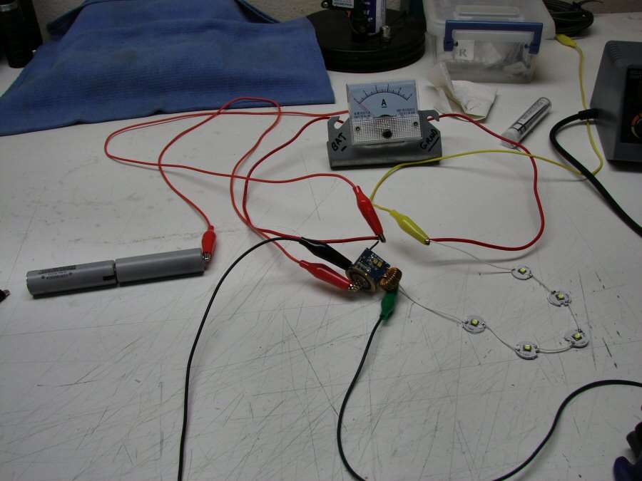
Set up to check amp draw to the leds
and Amp draw to the driver.
With Two 18650 batteries:
3.75 Amps going to the Driver on High
1.5 Amps to the leds on High
With Three 18650 batteries:
2 Amps going to the Driver on High
1.5 Amps to the leds on High
UPDATE: Driver Mod finished
I added the .68 ohm resistor and I got an increase from 1.5 amps to the leds, to 2.2 amps to the leds.
Then I did the .82 resistors (house style) and now I get 2.5 amps to the leds.
I think that's good enough. After all, it's just an Xmas giveaway light.
That is an electrical junction box cover. I love to use things for other than what they were intended.
I find that commodity items are cheap and sometimes offer a cheap and convenient solution to construction projects.
I would have to wonder how much added resistance all that wiring adds to your circuit. You may not be getting an accurate picture of what the draw would really be. If you are only interested in a before and after comparison then maybe it wouldn’t matter so much.
You could remove one of the R820's and remeasure to see how much current changed.
think if batteries at 3.7v load voltage,
with 3 batteries = 3.7v x 3 x 2A = 22.2W
with 2 batteries = 3.7v x 2 x 3.75A = 27.75W
that mean higher the input voltage, higher efficiency.
Now LED current confirmed 1.5A so
voltage drop in sense resistors 0.34 ohm x 1.5A = 0.51v
on this bench test, you can solder regular resistors and check LED current improvement.
for 2.5A you need 0.51 ohm, for 3A its 0.33 ohms.
2A - 2.5A more practical than 3A.
I would not bank on 1.5 amps to the emitter. Dchomak had a good point about all the wire and connections in the rig pictured above. It's quite possible that the driver will deliver the rated 2 amps in the light. Especially with O-L's skill at lowering resistance in a light.
EDIT: Added "not" above.
Wiring resistance can’t affect LED drive current because this is a boost driver. in here, boost convertor regulated to constant current. not voltage.
here simple test to prove that:
Add 0.5-1 ohm resistor series with LEDs
then check drive current again
Didn't realize that. Thank you for that info. In Post 26 above, don't you mean he needs about .2 ohms overall resistance to get 2.5 amps and .17 ohms for 3 amps? Resistance is already at .34 ohms.
yes he need overall resistance of 0.2 for 2.5A.
exiting resistance is 0.34 so we need 0.51 additional resistor to make 0.2 ohm overall.
So the resistors I just bought are no good… Well what happens if I use the 0.68 anyhow? I ordered .68 and .85 I believe. I can order others, but if I can mix and match from what is there…
As far as the amps from the driver to the leds, "all that wire" hooked to the amp meter is 14 gauge and with the length it is, the resistance would be minimal. The meter is hooked straight off the driver lead, then to the leds, so it reads right out of the driver. It probably is off from the batteries, but I bet it's not enough to be concerned about in this test. What matters to me is the 1.5 amp output to the leds with both 2 and 3 battery configurations. My concern is if the driver will take 3 amps. That's doubling up on the components there and I would hate to fry it.
Some of the leads shown were also just being used for the clips, to hold wires together, so they aren't in the circuit as such, just the clips, (which probably cause more resistance than the wires ).
).