tivo i sent u a pm about your driver
Any chance of somebody collecting all the assorted parts and selling them in kit form? Assembly is easy - smear some paste around, drop parts into place, hit it with some hot air - ordering small quantities of the parts that only cost so little from all over, seems like one person doing the ordering then reselling everything together would be much more efficient. ;)
once i hear back from tivo i might hear back on a quote on some boards ![]()
If you’re just using paste and hot air then shoot, I’d be in for a couple kits if available. But I’m looking for 2x18650 drivers mostly.
Yes, really easy. I use a butane soldering iron with no tip installed, it has a catalyst honeycomb thing inside that burns the butane so no flame comes out the end. Apply paste to all the pads with a toothpick (and in most cases it doesn't have to be precise, surface tension when it melts will pull the solder onto the pads and off anything on the board that isn't a pad), plop the components in place, then move the hot air around evenly over the board, components and everything, and when it gets hot enough the solder melts. Surface tension will snap the components into place on the pads, so alignment there doesn't have to be perfect either. Really neat to watch, the melting flashes across the board like a shockwave when it goes.
Shockwave? Sounds pretty cool! I’ve used hot air to clear boards before, but this sounds even better. Now that I think of it, I could re-flow emitters with the heat gun too. Probably run the heat from the bottom though. Then again, I might miss sharing the flashlight experience with my wife and her frying pan. ![]()
It's actually easier to put stuff together with hot air than it is to salvage stuff off a used PCB with hot air. Much easier. I think mostly because factory-made stuff uses lead free solder that needs way more heat, scorching can be an issue. Even flooding with flux and melting in some leaded solder before starting with the hot air doesn't always make it go smoothly.
The gate doesn’t need a pull-down if the processor output pin is driving he gate low (i.e. not an open-drain output).
In Eagle, you draw the board outline on the DIMENSION layer. You can make it any shape you want. Draw it with a .001” wide line so any confusion about routing the board to the inside/enter/outside of the line is of no consequence.
ThanksTexaspyro. Yes it’s not an open drain output. I think the purpose of the pull down is to quickly turn off the FET. But since I don’t see any problem including the moonlight mode we may not need the pull down resistor. ![]()
The chip should be able to drive the gate off faster than any reasonable sized pull-down… also a heavy pulldown resistor would limit the turn-on of the FET.
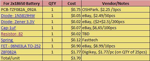
Here are the preliminary parts list. Unit cost are for references only.
Still for final testing when my parts arrives.
I’ll share the PCB design at OSH when final
I’ll also provide a DIY programming procedure when done.
For 1x18650 Battery (XLM, XPG, XRE…)
![]()
For 2x18650 Battery (MT-G2)
![]()
That’s awesome!
But it may not always be an output. ![]()
Between the time the supply is connected and the controller connecting the IO pin to its output stage, the gate is floating. At least if the IO defaults to input or some other high z state.
Some people might want to secure the circuit against that, at least if it is some kind of critical application.
But for this one I’d say it is fine without.
Unless of course you are planning on crashing the mcu with some funny code before the IO initialization. >)
Programming Summary for DIY:
One Time Setup:
1. Install the Zilog ZDS-Z8 Encore! 5.0.0 SW
2. Install the Project/Batch files for programming the driver
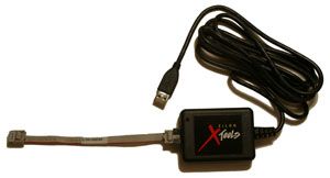
3. Build a 4-pins USB Programming Cable
4. Install the USB Programming Cable driver
Programming the LED Driver
1. Connect the 4 pins of the programming cable to the LED Driver and
the USB end to the Host PC.
2. Navigate to a specific directory and run the batch file (.bat)
3. Wait until it finish
When I’m done testing the driver, I’ll be posting a much detailed procedure.
Still waiting for parts!
![]()
Would it be possiblble to wire up a Micro USB like Pilot PTK did on his?
I was thinking of that too for the programming port but there’s not enough space.
![]()
What about bare pins instead of a socket? They don't have to be full length as it only has to make good enough connection while on the bench for programming.
Instead of pins I got holes on the driver and pins for the programming cable. It will be like this:
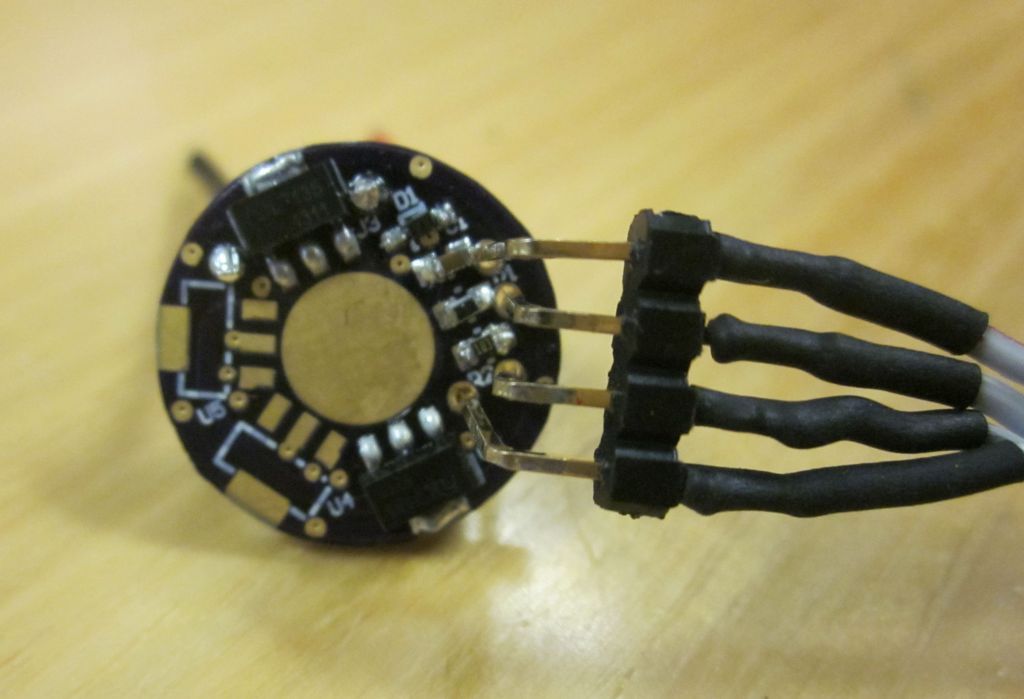
Believe me, it’s easy to re-program. ![]()
![]()
What programmer is needed for programming these?