7135 based driver on LiFePo battery? (=also IR light build thread, with measurements on Oslon Black 850nm led, mod finished now)

hmm, I did some testing on the led on copper tonight, I may at least want to go to 2A :evil:

Here's the underside of the led, the solder pads footprint is smaller than an xpg but I reckoned it would fit a xpg Sinkpad. I just reflowed it:

And yes, it worked (50mA from led-tester), a very faint red glow in reality but my phone camera (even though it will have an IR-filter) picks up a bit more of the IR radiation:

The central heat sink pad of this led is unfortunately not electrically neutral (it is connected to led+) so it will be an extra challenge to fit this board into a flashlight while keeping a well enough heat path from led to the outside.

The test set-up, with the luxmeter clamped-in close to the top of the led to pick up enough radiation to measure anything at this insensitive wavelength. Ledboard on huge chunk of alu, directly connected to power supply.

2.8 A :evil: :

And the data neatly put into a graph. The measurements are quick and dirty, as usual because of lack of time and motivation to do it well, but it all seems to make sense:

Of course the led had less than a minute (about 30 seconds) on the highest currents, but I reckon it should at least survive 2A for a while, even inside a flashlight :-) . The current really runs away with minime voltage rise, so I really want a good current regulated driver now.

Whats your plan for this IR emitter btw?

Member GMARSH made some custom Oslon PC boards for his high-powered TV-B-GONE flashlight… he might be able to supply one… The TV-B-Gone flashlight build

Couple notes, based on my experience with the TV-B-Gone flashlights:

- The IR Oslon’s have two dies in series, so their forward voltage is double a typical IR LED. At 2.8A, the 940nm SFH4725S that I’m using has a ~3.7V forward voltage. This means a single LiFePO4 might not cut it.

- The center thermal pad of the Oslon is connected to the anode, so make sure the sinkpad is electrically isolated from the pill when you build the light. I’d suggest using thermal epoxy (arctic alumina, etc) instead of fujik, so there’s a hard insulating layer between sinkpad/pill. Measure with a DMM to ensure the pill/sinkpad are isolated when you’re done, otherwise you’ll short the cell when you turn the flashlight on.

Thanks for the notes! The IR Oslon that I used is actually a different one, it has a 90 degrees beam angle (very round dome) instead of 150 degrees, and it apparently has its dies in parallel because the Vf is between 1.5 and 1.9V. It is part nr. SFH 4715S , I guess that your led is SFH 4725S. It makes my driver solution different from yours.

I will use arctic alumina adhesive to mount the led board :-)

I should have got the in series version instead of the parallel version, it would have been much easier to drive. But I did not know there was one until now :-(

I see in the thread that texaspyro linked that you put 2800mA through the (series) led. That would compare to 5.6A in my test, quite rough on the led I'd say :evil:

Ha, I didn’t know SFH4715 and SFH4715S were two different parts - S being the two-series-die version. If you’re using the non-S version, you’re fine with a LiFePO4 cell.

Both parts are rated at the same forward currents, interestingly (1A RMS, 5A pulse) - implying you can get twice the light out of the same package with the S version, even though the S version would presumably generate twice as much heat in the process.

Just caught texaspyro’s post - I mount my LEDs on a FR4 board, and I do have a couple of spares I could give up, but if your LED will be powered on continuously I’d say just stick with the sinkpad.

Oh; on a Nanjg 105C driver, remove R2 to disable low battery shutdown.

Instead of isolating the sinkpad how about switching the build to be host positive?

Battery positive to the tail. Isolate the ground ring on the driver from the host, bring driver ground to a battery contact plate, connect driver positive to led.

Did you have a host in mind?

A reference image might help with some of the mod suggestions.

I did not have enough time today for real flashlight modding, but I did test out a nanjg 105C on the Oslon, with succes :-) (after my output test and reading about gmarch's mods, I got greedy and wanted more than a ak47, but still thanks for the image Helios )

I zapped out the R2 resistor, as suggested by gmarch (edit: and ImA4Wheelr) (thanks for that!). Then wired the driver to led and 14500 LiFePo battery, with the current measured at the led wire (the wire colours look funny: I accidentally swapped red and black at the led board):

I used the third star and got 0.13A on low, 0.85A on med, 2.6A on high (close enough for me). The driver gets hot fast, as expected, I need to pay attention to that in the mod.

djozz wrote:

I zapped out the R2 resistor, as suggested by gmarch (thanks for that!).

You're welcome

Oh oh, apparantly I used a wrong word again ;-) , nothing personal.. (I lookedup "zap out" , it is nothing I intended to do to that poor resistor)

It sure is not easy for us non-native english speakers to just find correct words, and I am getting ever more careless about my language nowadays. (and I'm not even mentioning humour, we sound stiff and humourless in english)

There is something wrong with “zap out”? I’m a native english speaker & it seems fine.
Perhaps I’m not cool enough to know.

Google brings up urbandictionary for “zap out” but often people add junk to urbandictionary.

I figured you meant you removed the resister from the driver, which is what I first suggested in Post 13. I was just childishly feeling unrecognized as I did spend a little bit of time looking into the driver to get that information. But now, I see I left a zero off the resistance in my above post. I should have said 4700 ohm resister. The resister you removed from Bay R2 should have been marked "4701" which is 4700 ohms.

Ah, I see it was not my language that was the reason for the post.

And I'm sorry ImA4Wheelr, I am totally guilty of not recognizing you being the one to suggest the removing of R2 first (that was indeed marked 4701). The (bad) reason was when reading your post I was in the process of considering using a boost driver for AA, and so I did not read it very well. And when I was back on track with the lineair driver it was suggested again by gmarch. I will do better in the future, more carefully reading the suggestions people have for me .

I didn’t notice ImA4Wheelr’s suggestion earlier when I made the suggestion myself. 100% credit goes to him :slight_smile:

With the driver mounted in a pill, it should be much more manageable thermally. Also, most electronics parts will operate reliably at “second degree burn” temperatures - the Tiny13A and 7135s will happily run at 85C ambient according to their respective datasheets.

No apology necessary. Nice of you both for the respond how you did. I'm sorry for my over sensitive moment.

Please return back to this interesting build. Looking forward to watching it progress.

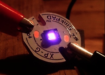
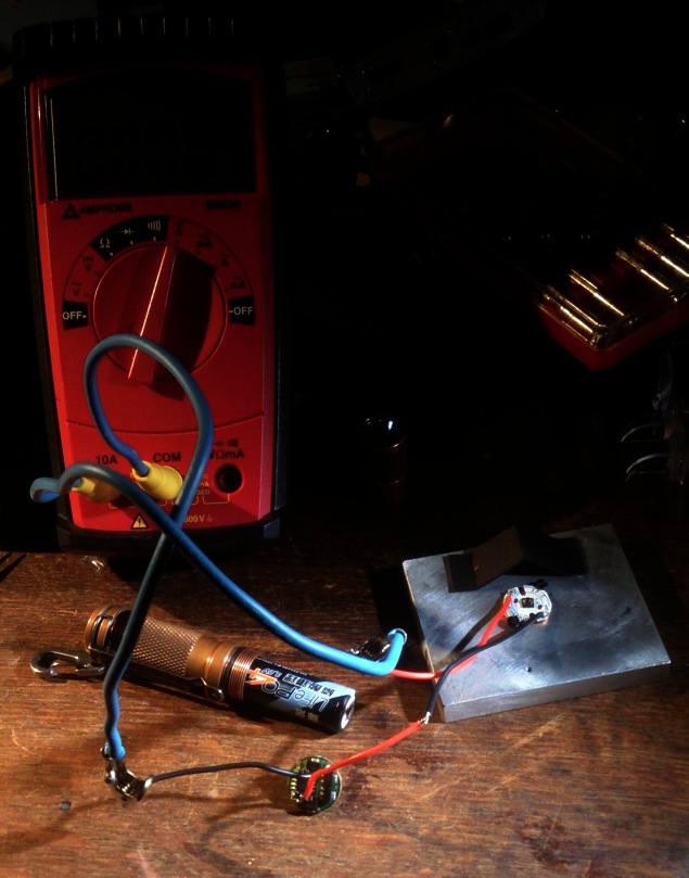
got a few more things done tonight.

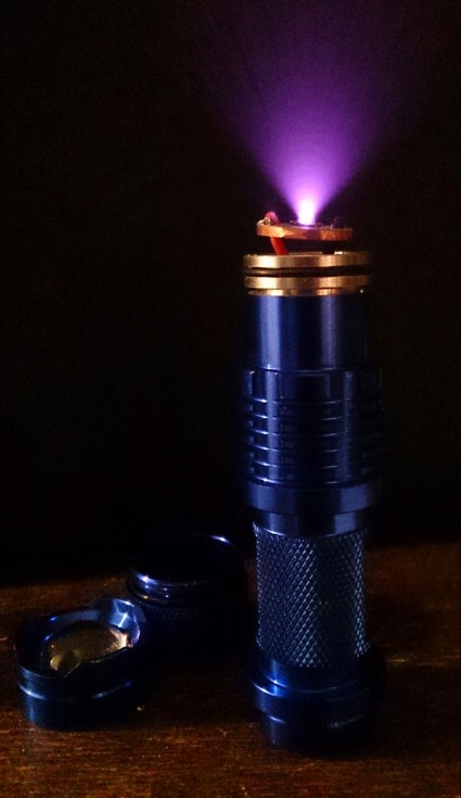
The electrical set-up works, what about the host? Performance-wise I should go for the empty (brass) C8 pill I still have somewhere, throw it all in and watch the throw if I put it in the Uniquefire T20 with a A123 LiFePo battery. With the 90 degrees output of this led that should match very nicely. But I just don't want the led there, I want to extend my sk68 clone collection, so this will be the host:

The cheapest Banggood coloured clone, they managed again to use less aluminium, even thinner anodising, and the lens came thoroughly pre-scratched. But I must say, where it matters, it is still good: it has the silicone o-ring under the slider, zooming is smoother and it is a bit more waterproof than with the metal ring; although it has a hollow pill, it has a good edge for the led board to sit on; and last but not least, it has a screw-in led-board containment ring, I like that very much.

Now, the sk68-and-clones have a 14mm driver, the 105C is 17mm, so it will not fit in the driver opening. But there is enough room (18mm wide) under the pill before it narrows to AA size, and if i saw a bit off the pil I can let the driver float there, I have done that before.

But what about the heat? Normally I would not do anything about it and just wait for the driver to fry or not, but since I post about it here I thought it would be neat to make a driver heat-sink path.

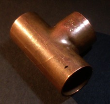
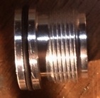
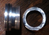
This copper sock is nearly 17mm outer diameter, I used two slices of it for the heatsink. But first I had to shave a corner of two of the 7135 chips to make room for this copper ring (two out of eight chips of the 105C are mounted further to the edge than the rest). Can this be done without damaging the chip? Apparantly, because it did not lower the output current of the driver. I also replaced the short spring of the 105C for a even shorter brass piece:

a lot of sawing, sanding, fitting, soldering and filing later:

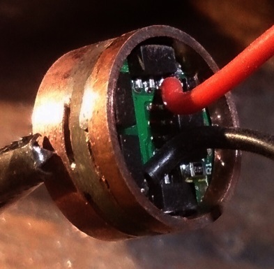
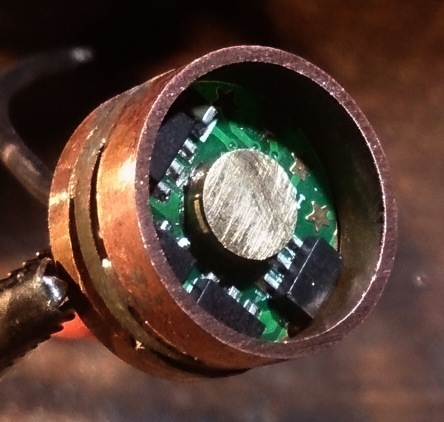
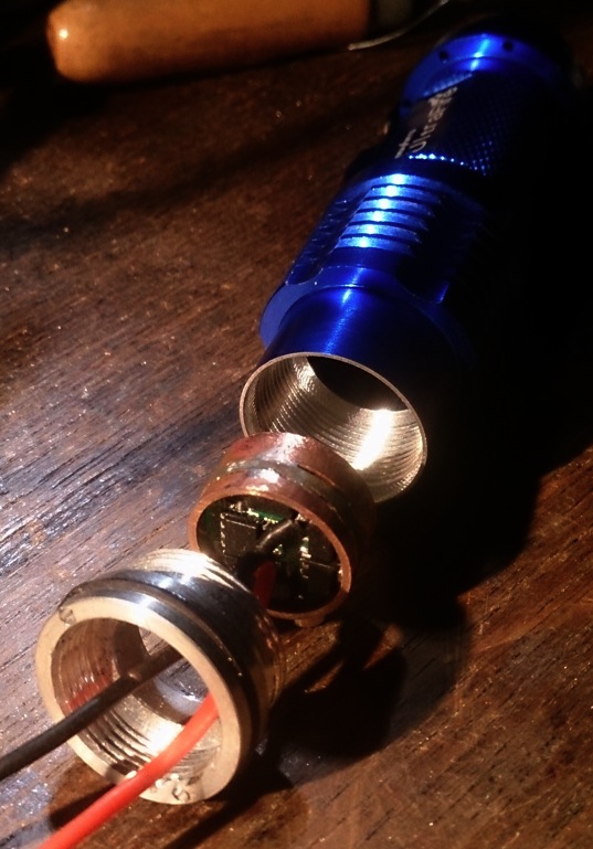
There is a small gap between the rings and the driver because the ring sits on top of the outer connections of the 7135 chips. It is 'tacked' in place by blobs of solder where the chips are (exept one, that I forgot). Had to use a small blowtorch to heat the copper to the melting temperature of the solder, while avoiding aiming the flame directly at the driver. Here is how the driver should fit inside the host, it will be screwed tight between the pill and the battery tube:

I soldered the wires to the led-board, but now I'm stuck because the Arctic adhesive that I need to glue the led board to the pill (which has to happen without making electrical contact between them, I hope that it will work!) is in the bedroom where my (disused) work bench is but also where my girl-friend is fast asleep at the moment (I need sleep too ).

First option for any progress will be sunday night.

That last picture is awesome. What’d you use for a camera?

Thanks, I like it too :-)

For posts here at BLF I always use my phone camera (at the moment a XperiaZ, it has a very ok camera). Phone camera's always do good close-ups because of the small diameter lens and sensor. I always pay some attention to the lighting of the subject and try to make the right cut-out, to make a picture look nice.