Ah too bad, so I guess the other generic chip is the controller?
Yeap that must be it.
i hope you are taking notes on this build
because when you are done ill be sending you a valuable sum in dollars to build me one ![]()
Hehe, I do have a spreadsheet of all the parts costs but I’m afraid to total it up for fear of what I’ll see! … ![]() :money_mouth_face:
:money_mouth_face:
Just hoping the final light will be worth it ![]()
Tested the driver circuits today. Zener modded MCU board is doing it’s thing and the individual 7135 slaves are supplying the expected 6Amps to an MT-G2. This thing is dangerously bright at that output level, hence the welding glass ![]()
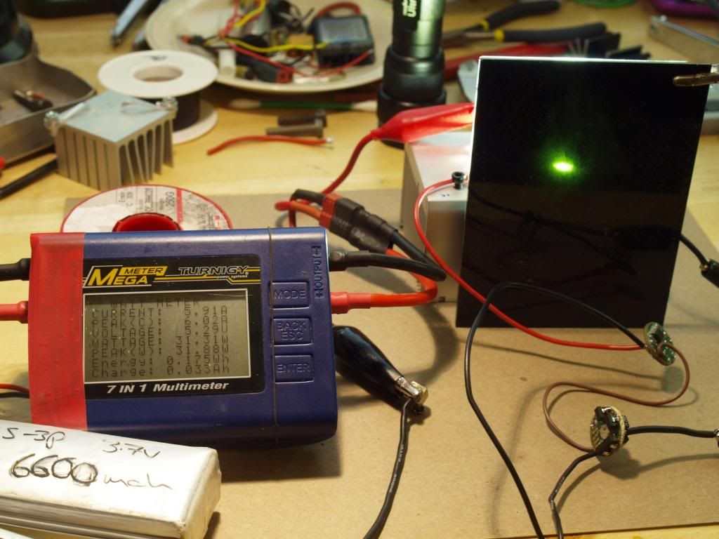
Lipos already slightly down after a bunch of testing, also crappy long test leads not helping hence the 5.9A on the readout. Started out stable at 6.02A.
At that drive current I measured 6.9v across the emitter so that is matching up perfectly with the graphs I was looking at. Should be resulting in well over 3000 emitter lumens too. :bigsmile:
-
Keeping an eye on the temperature of the 7135 board I didn’t notice anything too alarming running for 30s or so on high.
If my calculations are correct, on a fresh lipo input voltage of 8.4v, dropping to 7.6v once it gets to the driver and combined with this measured vF of 6.9v @ 6Amps, each 7135 driver board should “only” have to dissipate around 4.2Watts of heat.
This should be manageable and with deteriorating input voltage over time this will come down gradually from there.
In any case a little bit of heatsinking and I expect these boards should be quite happy running at these drive levels, that is until the massive amount of heat coming from the emitters overwhelms the whole situation anyway! ![]()
This is getting really fun now! ![]()
—
Edit: Don’t pay any attention to the Voltage or Wattage/Power readouts on the meter, the voltage reading on that unit has been broken since basically day one and as a result the power rating is also off considerably. Current reading is thankfully still bang on and very useful ![]()
Ok, some progress on the driver mount/heatsink.
I found an aluminium piece from an old school project that was exactly what I was looking for. I ground the OD down a bit so it would fit nicely into the driver cavity,
drilled 3 holes through the edge for the LED - wires and heavilly countersunk the center so the reflector retaining bolt could sit inside the piece neatly below the drivers. I should still be able to get my allen key in between the driver boards to the tighten/loosen the reflector bolt. It’s a bit messy right now with all the excess wiring but it should work ok.
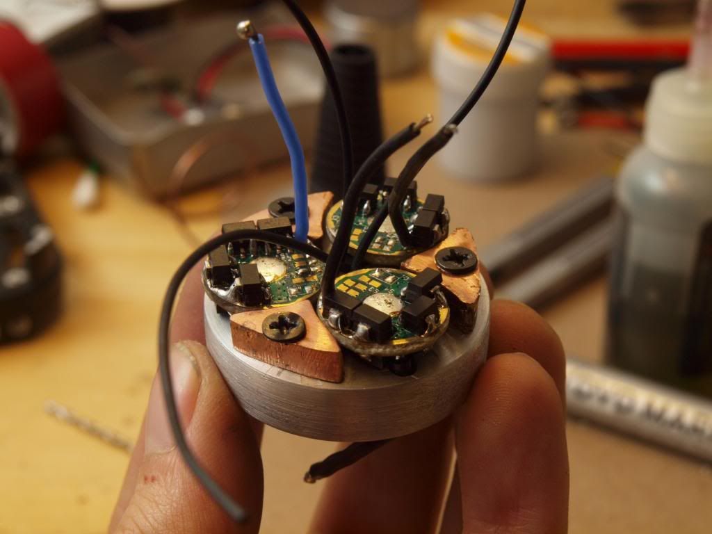
The copper pedestals/retainers I made out of some of those copper tabs I had ordered for creating the thermal path between the emitter plate and the reflector. I reflowed them together and cut and filed them down to act as retainers for the boards. The top of each copper pedestal is flush with the driver board ground ring so I will solder some connecting tabs between the pedestal tops and the ground rings. This should hold the boards securely in place, act as the primary heatsink path for the 7135s and also supply battery negative/ground for all the drivers.
To get battery negative to the pedestals I’ll probably solder some relatively fat supply wires directly to them.
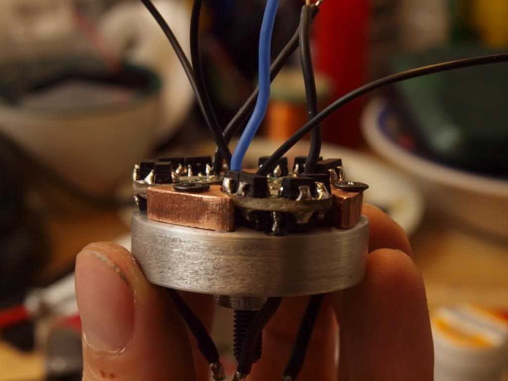
For the positive side of the circuit I’ll just run a single fat wire from the contact board through a hole in this driver board holder (which I still need to drill) and split it from there to the individual leds.
I have a little standoff on the bottom of the driver mounting assembly that will give me enough cavity space between it and the emitter plate to route the individual LED supply wires.
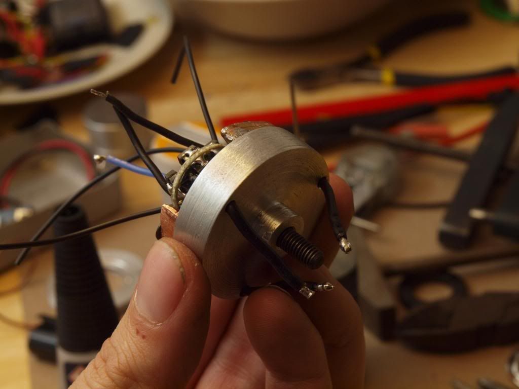
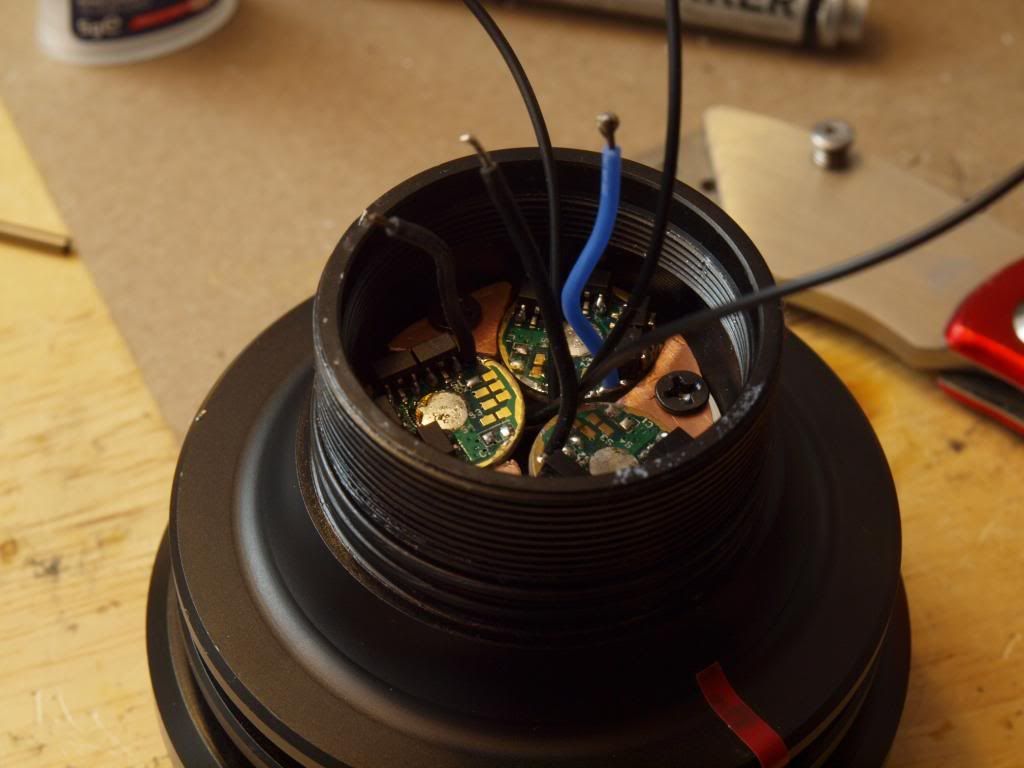
Here is the whole thing dropped into the driver cavity. It’s sitting considerably higher here than it will end up because the LED - wires are in the way. Haven’t drilled the led wire holes into the emitter plate yet.
Annoyingly once I had everything test assembled an LED - cable broke off and took the solder tab off one of the driver boards. So I need to fix that, those KD 7135 boards are a bit crappy and weak in that regard I’ve found. Similar thing happened on my Apex build, maybe I should have just sacrificed a few Nanjg 105s to build these slaves…
So that’s it for now.
Next I’ll look at the battery carrier modifications to deliver power from the XLR power input to the driver section. I won’t be attempting to make it 18650 compatible at this stage so that should be relatively straight forward. No way I’d get it all finished before the end of modvember otherwise! ![]()
Cheers
Linus
Yuk, did the same thing a couple of times on those KD drivers -- I don't use them ever, anymore... Even the 7135's are laid out better on a Nanjg - just find them easier to work with overall, cheaper, besides the programmability  .
.
This build is look'n good! Coming along...
Yep glad to see the back of them too, that’s the last 3 I had left over ![]()
AWESOME BUILD MAN… hoping to learn something here…btw i’m new here and greetings everybody…
Thanks chris and welcome to the forum!
That battery pack is really something. Inspiring a dream of a lantern for camping with a battery pack that could be similar. Keep up the great work.
Chris, welcome to the forum!
Linus, you have continued to make good progress on the build. I like that you are taking your time and laying everything out cleanly. This is an awesome build.
Thanks Richard, working on the modified battery holder and power delivery system at the moment and it’s taking longer than expected to get everything right. Needs to be able to deliver ~20A through a twisting contact interface to the driver contact board as well as provide a twisty contact for the trigger switch circuit. It’s fiddlier than I thought it would be but I think I finally have something that will do the job.
Still waiting on the small rail to mount the handle properly to the battery tube. The first one I ordered from ebay never arrived and the reordered one from DX is taking it’s sweet time to get here as well. That’s the biggest obstacle for getting this thing finished by the end of the month, provided my modified battery carrier/power delivery setup survives the full power test in it’s current form anyway. ![]()
Boy … you are creating a monster!
congratulations! truly a wonderful job! ![]()
When you turn on the T-REX, I see it from Italy! hahha
What a Zener diode, you have to buy to replace?
Wow!
The zener I used is a standard 4.3v 0.5W one, not the surface mount version although those will work too. The key thing is that the voltage to power the MCU is kept below 6v and since a fully charged single cell delivers max 4.2v the 4.3v zeners are very close to the ideal. Anything in that range will work fine though.
Here’s where I got mine.
Zener 4.3v ebay

Haha! :bigsmile:
Ok, It’s been a while but I’m finally making progress on this build again.
I’ve finally been able to retire the cable ties and assemble the proper handle mount!
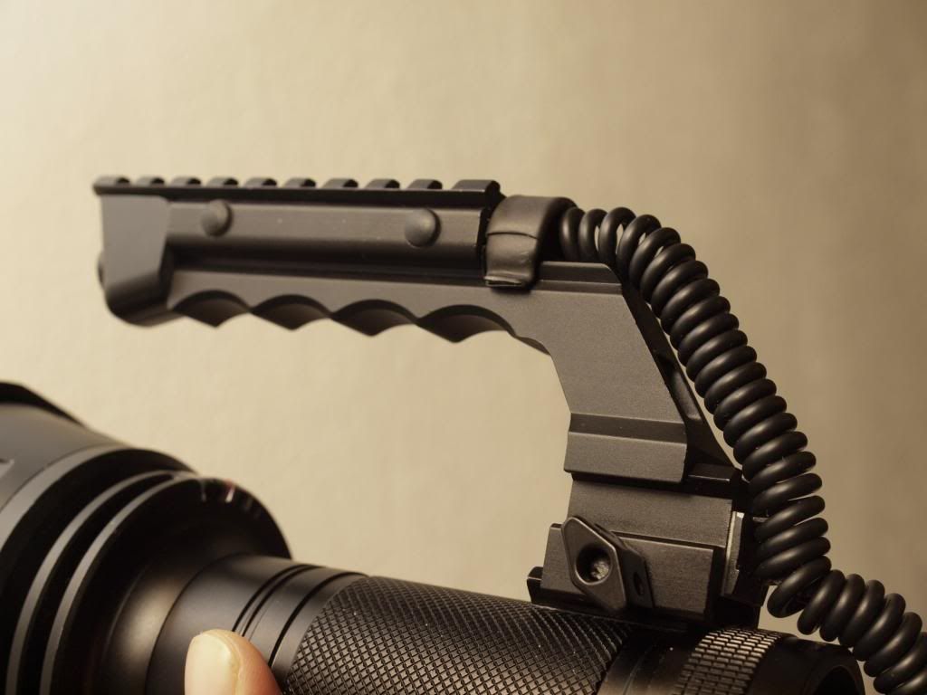
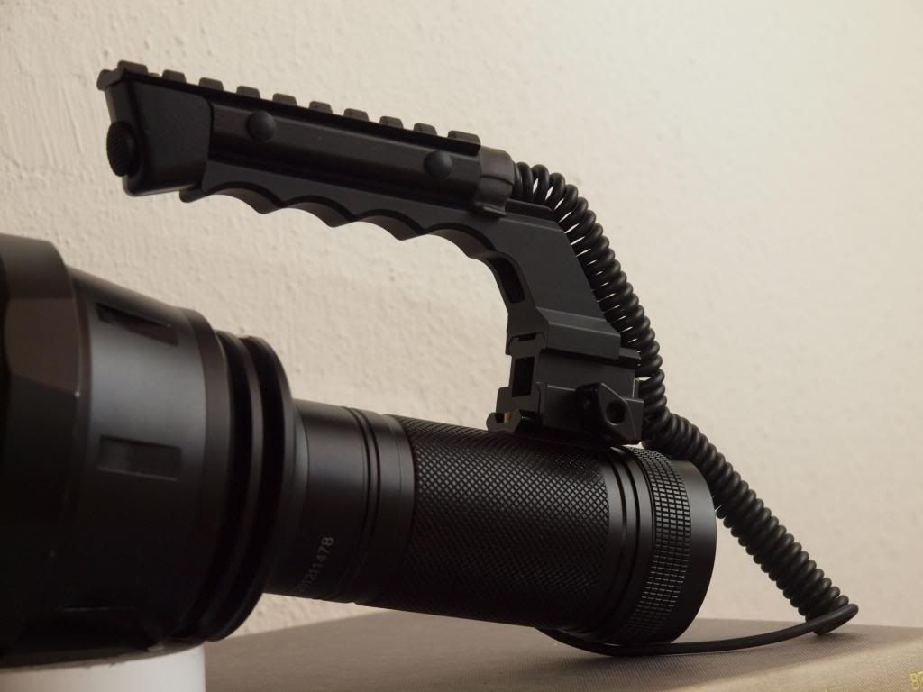
This tiny rail part took the longest to get here and it was the first I ordered…![]()
Original Ebay order went missing and had to reorder it from DX which took another month to get here, of course it also looks like a dog chewed on one end before it went to anodizing but hey you can’t have everything can you ![]()
Anyway I wasn’t going to let this part hold up the build any longer, the battery tube is drilled and tapped and the mini rail is bolted firmly in place with brass M4 bolts.
At least the dodgy end isn’t visible when assembled ![]()
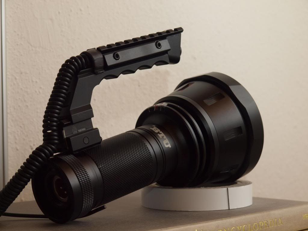
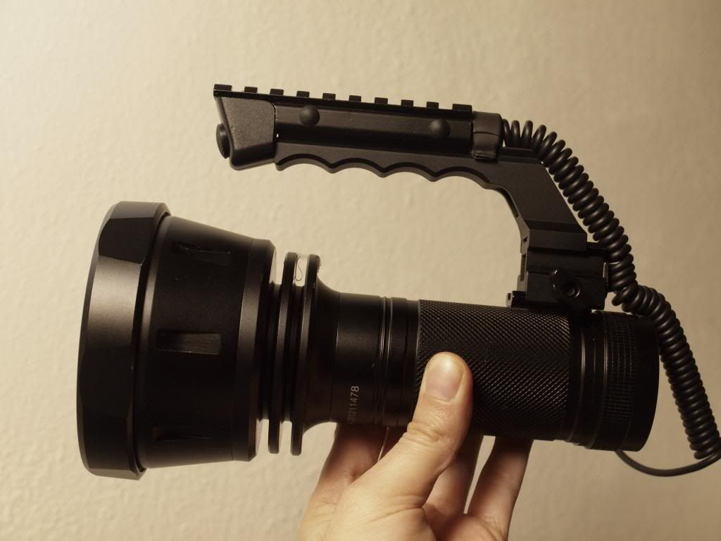
Very pleased with the handle now, it’s a fair bit lower to the light body than with the temporary mount and while I got used to that setup, this is just about ideal.
Haven’t tried it with the reflector in yet but balance shouldn’t be much different to before so that should also be fine.
—
Next progress update is on the internals. These have been holding me up as well, but more due to their complexity than any missing parts.
The main problem was in transfering close to 20 amps through a turning interface contact to the driver electronics in the head, and doing it with as little contact resistance as possible.
This is what I’ve come up with…it’s still a WIP and haven’t tested it at the full current load but I’m pretty sure it will do the job nicely
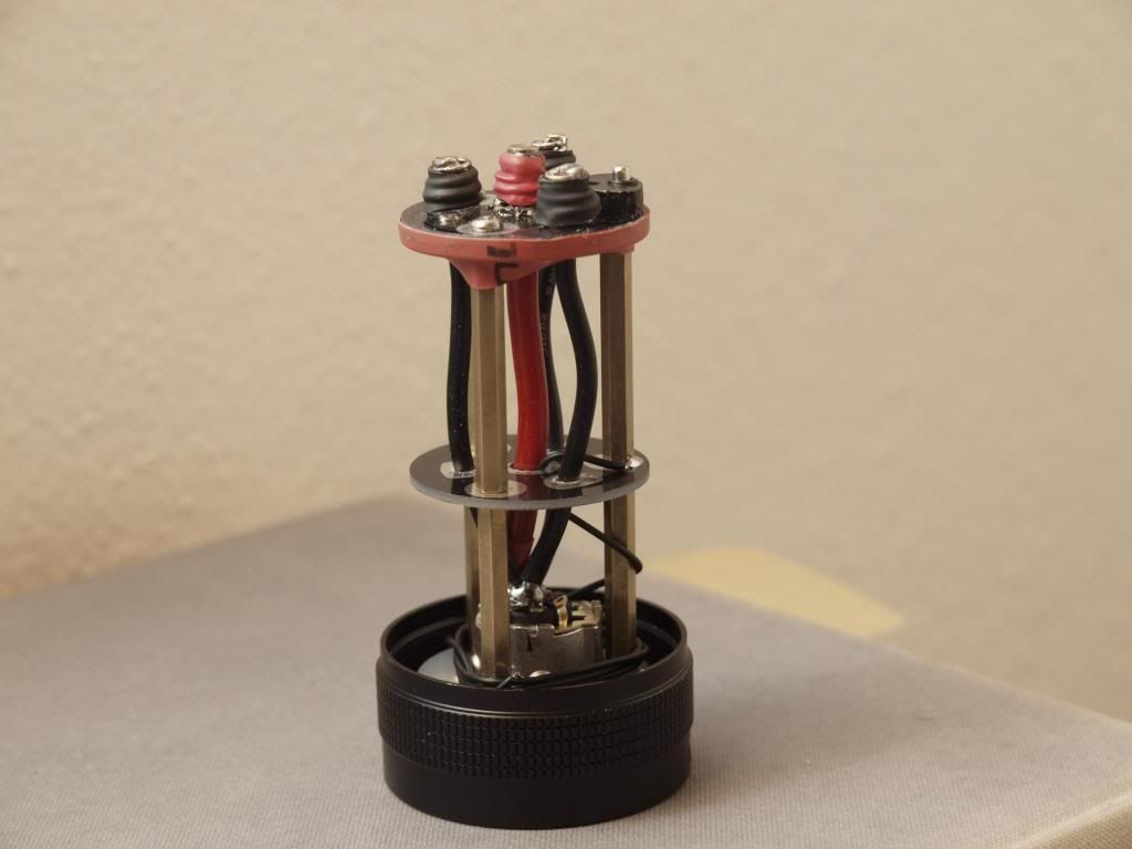
This is the reworked battery carrier, the xlr socket is firmly bolted to the tailcap case and the carrier assembly has been cut out and sunk around it then hotglued in place.
I also split the boards up to add one in the middle and increase the torsional stiffness of the assembly a bit.
On the top I have 4 contact posts, these are made of fairly stout flashlight springs from cnqualitygoods and each one is heavily beefed up with copper wire to maximize conductance. The springs aren’t really very springy anymore but that’s how it should be, it just needs to make a tight press fit against the contact board without being too rigid and breaking anything off while being tightened.
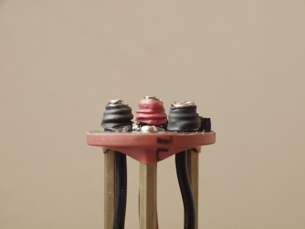
I have 3 springs/posts for the battery neg and 1 central one for battery positive.
This central one is even more heavily reinforced with copper wire and soldered to the top is a brass cylinder which will make the contact. It will also act as a registration and centering pin for the whole assembly.
Currently they’re wrapped in shrinkwrap to avoid any potential shorting issues due to bent springs, but I’ll probably go a bit further and glue a short plastic ring around the base of each post just to make sure nothing can jump across and short.
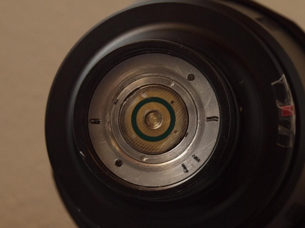
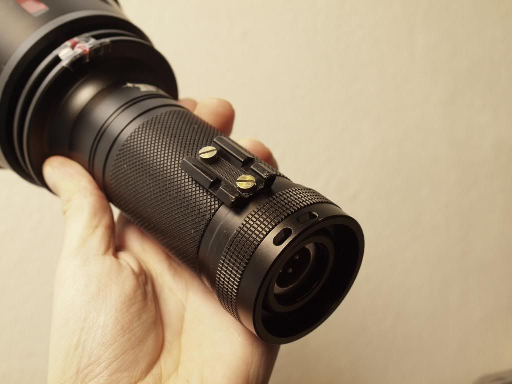
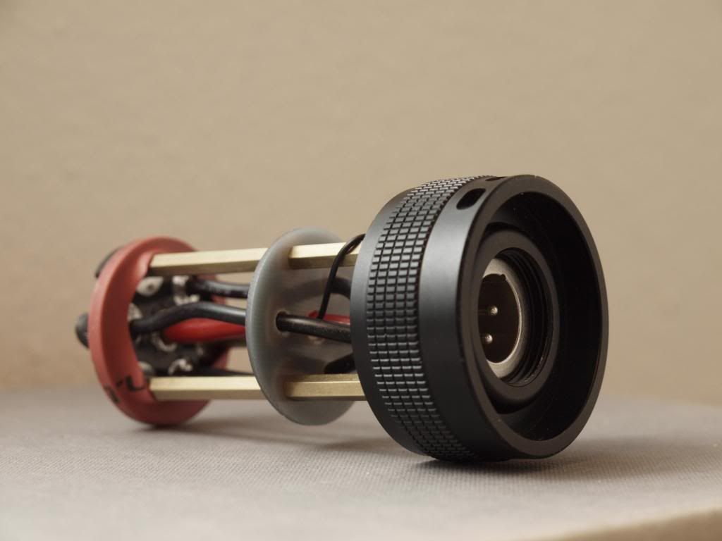
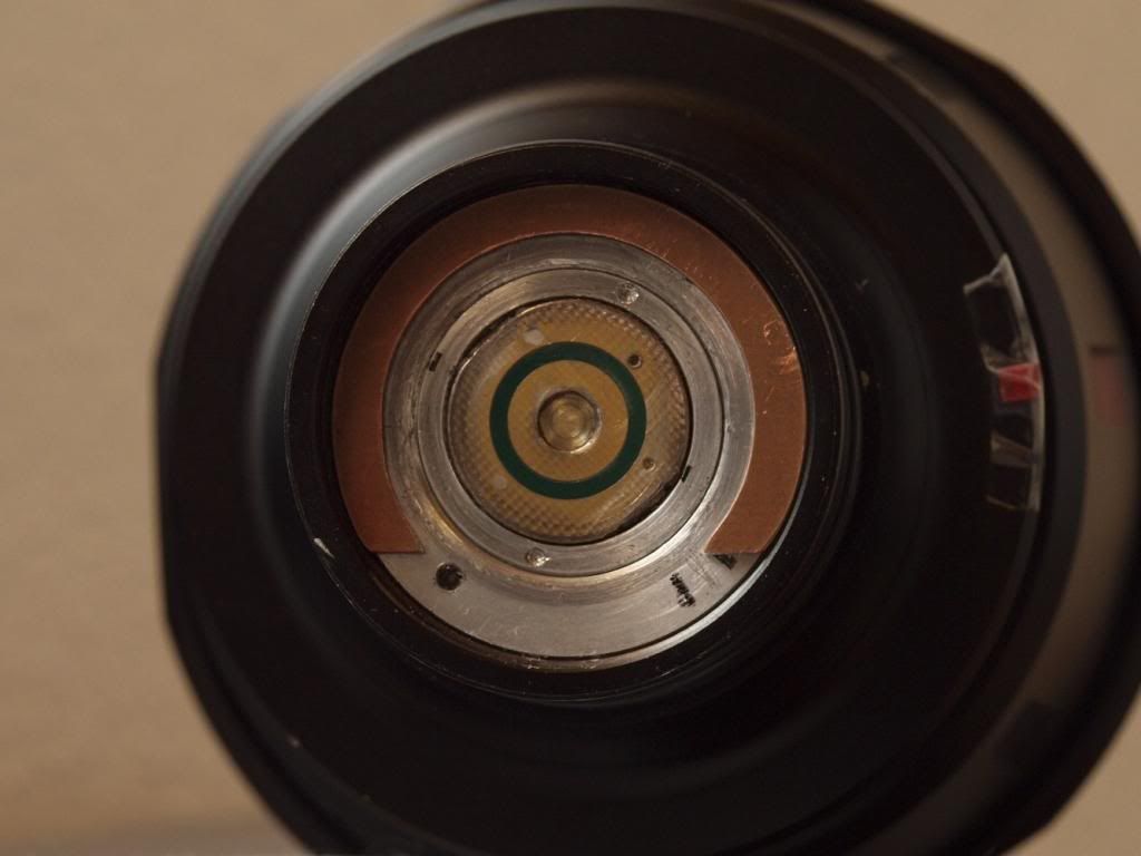
On the opposite side I’ve reflowed a 20mm contact board to a copper wire extension so it could be clamped into the stock driver retaining ring, then soldered another brass cylinder into the central hole with a small depth offset to which the main battery positive wire for the driver is connected.
The small cylindrical recess created in the center offers a registration/centering point for the battery positive contact post as well as hopefully a good tight contact surface.
You can see the polish/wear marks from the negative posts on the aluminium edges of the contact board, I’ve tested the tightening of the assembly over 50 times while working on this thing and it’s doing very well. You can hear the click as the “centering pin” battery positive post engages with the contact board and then it tightens smoothly but with a healthy pressure resistance all the way up to the end of the threads.
The final part to this twisty puzzle was how I would complete the circuit for the clicky trigger switch in the handle. This needs to deliver or interrupt the power going to the MCU side of the driver and therefore needs it’s own contact post/surface combination on the contact board.
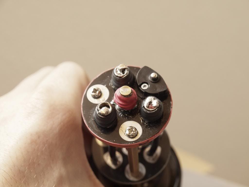
My current approach for this…and it’s not done/working very well yet… is using a spring loaded little contact post on the battery carrier side (made from a cheap 3x AAA battery carrier) and a circular copper contact surface made from a pcb board material on the contact board side. At the moment the contact surface is just too wide and interfering with the battery neg posts but I can probably work it down some more. It’s also a bit too thick so might need to find some thinner pcb board material or try something else…
An alternative that might be simpler is to go with a magnetic reed switch approach, tiny reed switch glued to the outside edge of the contact board or even behind the contact board? And a coil connected to the trigger clicky on the battery carrier, positioned where I have the spring loaded contact point assembly at the moment…
…so if anyone has any thoughts on if/how best that could work here please let me know. I don’t know enough about reed switches and coils to know if I would even be able to generate a sufficient magnetic field in this type of setup.
In any case I’ll do some load testing of this setup soon and if that passes without a fire I’ll finally move on to installing the critical components! ![]()
—
A simple test assembly has convinced me that I need to at least drill a registration pin hole into that damn reflector and add a pin to the emitter shelf so that it doesn’t all twist when assembling the head. I also need to add some handles or something onto the reflector so I can lower it into the head precisely without fear of dropping that damn thing on the emitters! Not to mention aligning and drilling the emitter wire holes and potentially pcb screw holes will take a lot of patience…
I also have my copper spacers to heatsink into the reflector done and waiting but that’s another variable that needs to be accounted for when laying out and assembling it all…this whole part should be a lot of fun if I prepare it all properly…but I’ll also be really glad to see the end of it for sure!! ![]()
Cheers
Have you thought about just running enough length of heavy gauge wire to absorb the twisting of the tailcap on, and then having everything solidly connected with no sliding? I know length of wire increases resistance, but you’re already using that phone cord to connect the battery to the light, a little more length of wire wouldn’t hurt, right?
Alternatively, why not use small springs to suspend copper rings? That is, have a smaller copper ring mounted on springs at your existing + connection points, and then have a thinner, wider ring around the edge similarly supported by springs for the negative connection? Solid electrical path into the copper rings, you have enough give that the rings would press 100% into the contact rings on the underside of the board.
Wowsa. One word only to describe your light at this point. Sexy.