Just checked again, they are perfectly identical in size.
He he he!!! With unregistered Post you never know what's going to happen! Actually, I placed an order for some 110v E27 base ones the same day (which came with tracking) and they also came today.
So I overlooked a key factor here… There’s great detail on how to wire the leds in parallel, but not how to physically connect the lamp assembly to the maglite switch assembly.
I too am curious how dchomak wired to the Maglite switch. BTW - I've done nothing with my bulbs. I'm just too busy to get to this and I don't even have a 3D Maglite yet.
I was thinking to solder the positive to the little spring cap that the underside of the incandescent contacts. Then solder the negative to the inner wall of the housing for the incan bulb. That seems to make sense to me, but I’m not very keen as far as electricity goes.
Edit: The spring cap looks like stainless, dunno if solder will stick.
Drilled spot and bottom of the board, or pos/neg at either side of the trace and bottom of the board? I see continuity when measuring from bottom of the board to either drilled spot, but not between pos/neg of the led blobs to the bottom of the board.
Great job! So you broke the glass off an incandescent bulb and attached to the internal wires to make your power connections? I only ordered warm, but then I also bought the FastTech Bridgelux LED's to replace with.
Yep, first one was a pita. Broke glass, slowly dug out the material between the remaining glass and the housing, accidently broke the epoxy/black gunk at the bottom trying to drill a hole through it…
Second one was a breeeeze. I found out the ‘weld’ is actually just solder on both the bottom contact and the side ground spot. Wicked up the solder, broke the glass, drilled out the remaining glass and yellow/white filler crap. Black gunk at bottom 100% intact. There’s a small metal cylinder insert embedded in the black gunk where the filament went through the bottom; with the solder wicked away and filament removed some tinned 22awg fits right through, solder it up and it looks factory except for the wires sticking out the top. I attached the negative to the outside wall of the housing; older bulb had 1 filament attached here, but the newer bulb it was attached somewhere inside the housing.
You can see my professional soldering here:
I haven’t slept yet; still riding the awesome feeling from getting these mags upgraded!
I took the switch out and soldered my wires to it. Your way is better, no need to take the switch out and you can quickly and easily switch back to the stock Maglite! Good job.
I am still waiting for my new, “designer” MR16. I ordered it 11/2 and it is still not here.
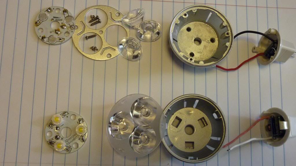
Here is a pic comparing the older lamp on top vs the new one on the bottom.
The stars and the drivers are identical. What is different is the lens, heat sink and plastic base. The heat sink is a little less beefy, but still the same size. Now instead of screws holding everything together, everything simply snaps together.
Because the stars are the same, I can merely swap my old modified “9W” star for the original and I am all set.
5 minutes later, done.
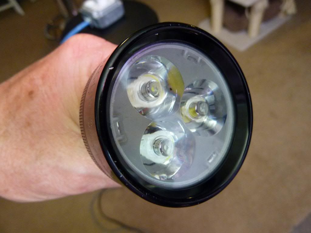
I think this looks much nicer, in fact it would seem that I spent hours working on it, but not so! I think this is a nice upgrade, even if you have already done the mod.
This is VERY important. The LED’s from the previous MR16’s must of had a Vf of around 3.7V. These newer ones seem to have a Vf of around 3.2V
I connected a bench supply to the driver from this new lamp and measured the voltage at the supply, to the star and the current flowing through the 3 LED’s in series (unmodified star). I varied the power supply voltage from 12V all the way up to 24V with no problems. In that range the voltage to the star and the current flowing through the emitters was constant. This is good news. The driver never even got warm.
Old star, voltage across the 3 emitters was around 11V. Current draw was .30A
New star was 9.5V and .30A
So this means that those emitters will probably blow up in a 3D mod. The GOOD news is that they are perfect for a 2D mod! I just checked, one emitter draws .30A with 2 D cells in series DD.
Are you referring to the Bridgelux emitters in the "old MR16" or the original emitters before the Bridgelux? I assume the latter. So what kind of vF do the Bridgelux have? Must be fit for a 3D as that's what you been running them with. (You do have them running DD with no driver or resistors at all, right?)


 The Traces look a bit different to OP's -->