Can the battery tube be reversed, so the anodized threads go at the front?
Not directly, the threads are the same on both ends but the tube isn’t completely symetrical. So for example the front of the battery tube has a deeper recess than the rear where they mount the spring pcb. Could probably be made to work with some standoffs though.
Also from what I can tell the front of the battery tube body only makes ground contact to the driver through the threads itself. It doesn’t press up against the grounding ring of the driver board directly as is usually the case in other lights of this setup.
It’s probably why I had the flickering problem at the start.
Poor grounding contact only through those solder blobs on the back of the contact board, relies on combined pressure from the press fit and the batteries to make contact. Another area for improvement ![]()
So I don’t think lockout by unscrewing the battery tube a turn or two is going to be a possibility.
Small update:
Was tinkering with the light and taking some tailcap/emitter current readings tonight.
In stock form I was getting a stable 2.58A at the tailcap.
Emitter measurements went as follows.
Meter connected with long thin crocodile wires clipped to the original tiny emitter cables gave me 2.04A at the emitter.
Ditching the crocodile wires and soldering my thick meter leads directly to the thin emitter cables gave me an initial peak of 2.69A but then dropping to 2.58A.
The fact that reducing the wire resistance increased the current indicates that this isn’t a true constant current buck regulator right?
Or do I have that backwards?
Upgrading the emitter wires from stock to 20Awg raised the tailcap reading to 2.9A, I also managed to get a voltage reading of 3.17v across the emitter in this setup (that doesn’t seem right to me, going by the datasheet I should be seeing closer to 3.3v to get near 3A).
That’s the last measurement I took before I accidentally shorted the emitter positive across the reflector and blew something on the driver, at that point I only had a firefly mode high and low. All modes still worked but at severely reduced output…![]()
Looking closely at the driver I noticed the supposed sensing resistor (R200) had a burnt mark in the middle and measuring it’s impedance gave me in the region of 50 Ohm.
Ok so I figured if nothing else had been damaged I could just replace the burnt resistor and might as well do some resistor modding while I’m at it.
So I took some of those smaller R500 resistors I had around and stacked 4 of the buggers to replace the R200. Should give me a total value of 0.125 Ohm.
Tested the light and there was lots of light again, the driver was alive once more ![]()
Maybe a bit brighter but hard to tell so I took some more tailcap measurements to check. These are a bit weird and I’m really not sure what’s going on anymore. I now get values that start at 2.8/2.9 and steadily rise to over 3 at the tailcap, max I measured was about 3.4A.
I guess the increase is somewhat consistent with the resistor modding but the rise has me baffled…before the mod it was very stable at 2.58A…
Anyway, I don’t really know what I’m doing with testing these kinds of drivers and this whole thing has left me more confused and disheartened than enlightened. The driver may not be working 100% after the short anyway so I would definitely take my values with whole lot of salt…
In any case I will soon be tearing the components off this board and getting a linear driver in this light instead.
So much easier to understand and control ![]()
Cheers
Likely not a buck driver, that would be pretty pointless in a light with a max Vin of 4.2v. Try it with 8.4v and a XML, or 12.6v and a MTG2... doubt you'll get anything but fried parts.
'Constant Current' is a different kind of thing from a buck driver that outputs a constant current. 'Linear' and 'CC' are describing the same thing, somewhere along the line some buck drivers got the incorrect CC label attached to them.
Making it lock out at the front like a SRK is possible, in theory at least. Isolate the driver from the head, add a larger OD contact ring onto the driver's ground ring. That way it doesn't matter if the head is connected to BAT- through the threads at all times, as long as the connection between the battery tube and driver is broken it will be locked out.
Just stopping in to say thanks for the teardown.
Mine should be in my possession tomorrow! My level of knowledge with this stuff is minimal so I will be waiting for proven results and I’ll follow someone else’s mod guidelines for this light rather than experiment ![]()
Definitely considering an xpg2 on copper and adjusting the focus to start things off.
It doesn’t have any cooling fins tho. How much amps you think it will take?
Yeah should be possible if you do it like that, although you may run into issues with battery clearance once the contact ring is high enough to press against the battery tube.
I tried adding some tall solder blobs onto the battery side of the contact ring where the little ears are. Just to try and increase the height and make contact with the battery tube edge, but after a certain blob height the batteries started hitting them when screwing on the tube…and I still wasn’t making contact with the battery tube…the gap on my light is pretty big it seems but ymmv.
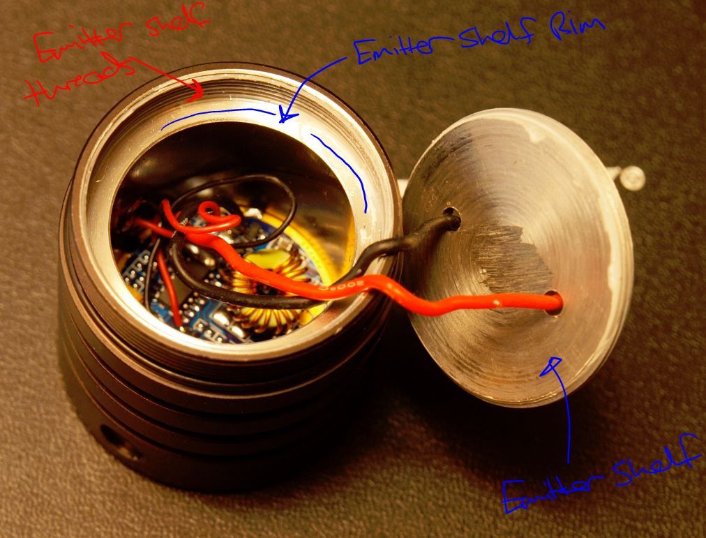
The emitter shelf is the main bottleneck really, I wouldn’t drive the light above 4A without taking some serious time to beef up the thermal transfer of that thin emitter shelf. Even at the roughly 3A stock it’s really not adequate…
The heatsink/driver section of the light isn’t particularly massive or well finned as you point out but it does have a decent thermal path from there into the fairly massive battery tube through the raw aluminium threads. Thermal transfer forward into the rest of the head isn’t ideal because the threads on the two part head are anodized, but the combination should still suck a fair bit of heat out of the pill and dissipate it pretty quickly.
I don’t see any real problem with the kind of power you need to dissipate from a single XP-G2 or XML even when driven at up to 6A it should do fine.
Provided the pill is improved anyway.
I just retested this one with 3x 20Rs in parallel. It, well, sorta works. It's not entirely happy with the voltage, it makes a truly wicked squeal from around 40% up to 80%. It's fairly quiet at 100%, but still making some noise. It only sounds not too bad because of how loud it is before it gets to 100%.
Output is 4.10-4.15A, shorting the big sense resistor on the top board only bumps it up to 4.30A. It is much happier at 8.4v input and above, though I don't think it would be unsafe/unreliable at 4.2v. The squeal is from the driver itself, not any of the connections or other components. No squeal at 8.4v.
How wide is the top circuit board? That may be the biggest hurdle to getting this to fit.
1.31"/33.something mm.
The inside surface of the lower board has components out to within .070" from the outer edge, so the ledge the driver sits on can't be any wider than that.
I love this beast ![]()
on the left is the big head with dedomed stock emitter flowed onto noctigon, replaced wires, braided springs, r100 sensing resistor and smaller centering plastic
on the right is t08 dedomed xm-l u2 1c on noctigon, replaced wires, some resistors stacked up…
and damn! this thing throws ![]()

also I turned the emitter plate upside down to be able to focus better (get the led deeper into the reflector and create some pressure on the board) and pasted it a little - then tightened it really well
but I screwed up the stock driver a bit, it doesn’t turn completely off ![]() measured ~16ohms between L- and ground and couldn’t find where was it coming from
measured ~16ohms between L- and ground and couldn’t find where was it coming from ![]() oh well, it’s a nice nightstand light when “off”
oh well, it’s a nice nightstand light when “off” ![]()
good to see some more of these lights in the hands of modders!
The hotspot it produces really is very nice once focused, dedomed it must be a beast. Nice one!
Did you manage to get a reading of tailcap current after the r100 resistor change?
Cheers
not yet, I’ll try to get a good reading this weekend across the tailcap
the hotspot is really nice, with a bit of flares
it got a brighter ring around the hotspot but that doesn’t bother me that much and I will not mess with the focus no more
Pretty much what I am planning to do with mine. The XP-G2 version will be using either an R120 or R150 resistor. I am not entirely too sure yet.
How are you finding it handling the added heat? Do you think it’s necessary to add some more heatsinking mass to the LED plate/shelf?
[quote=Rod911]
On my light I would say yes it’s pretty much necessary for higher output. Definitely for overdriving an XML to the max. Maybe not for XPG but the stock solution is really not ideal.
janko.hrasko how was the tolerance of the pill shelf threads on your unit?
Mine was very loose, as in I could wiggle the shelf easily and by quite a large amount when it was partially threaded on and in the focus position, that’s the worst thing about the thermal transfer I think. Very few threads for a small contact surface, and loose as well. Putting thermal grease/paste on the threads helps but not enough really.
the shelf was very loose on mine in the focus point too… that’s why I flipped it upside down to tightly screw it against the rim underneath it
in stock there was a recess in shelf in which the led was sitting… now it’s higher on the flat part of the shelf and even the reflector is pressing on it from the front
the heat transfer seems fine to me, it’s getting pretty warm but not hot even when I’m not holding it - the whole massive body is working as a heatsink
Yeah nice idea to flip it over, that’s probably going to result in the best solution using the stock components! ![]()
Is there any chance you can take measurements between the bottom of the LED shelf once it is screwed in and the top most driver components? It looks like the clearance is around 30mm, but that is a total guestimate.
Sure, I’m stripping the light down again in a bit so I’ll take a bunch of internal measurements of everything
Ok here is what I came up with.
| top of emitter shelf from top of heatsink when in focus | ~2.7mm |
| thickness of emitter shelf | 3mm (3mm-0.85mm for pcb cutout) |
| - | |
| depth from top of driver board to emitter shelf rim | 27.5mm |
| depth from emitter shelf rim to electronic switch port | ~12mm |
| driver cavity inner diameter | 34mm (33.98mm) |
| - | |
| emitter shelf thread O/D | 41.75mm |
| I/D of emitter shelf threads in body | 41mm |
| depth of emitter shelf threads in body | 7mm |
| - | |
| thickness of driver board | 1.6mm |
| height of driver at highest component (including board) | ~12mm |
| - | |
| diameter of flat base section on reflector | 27mm |
So Rod, if you want to know exactly the distance between the bottom of the emitter shelf when it’s focused and the top of the driver board.
It’s…
distance from top of the driver board to emitter shelf rim (27.5mm) + depth of emitter shelf threads (7mm) - gap from top of threads when emitter shelf in focus (2.7mm) - thickness of emitter shelf itself (3mm).
And if I didn’t mess any of that up it comes out as 28.8mm, so your guesstimation was pretty damn close ![]()
If you’re wondering about the size of the copper slug you could fit in there though, you’d have to take into account the height of the toroid on the driver (around 11mm) and the electronic switch port which is only 12mm down from the edge of the emitter shelf rim.
-
Easiest heatsink enhancement I think would be a 34mm X ~13.5mm slug (copper/aluminium) lapped and bolted to the bottom of the emitter shelf. Then drilled to accomodate the two emitter wires.
Starting with a 35mm bar it should be fairly easy to sand the O/D down a bit and also remove the anodizing on the inside of the driver cavity walls (and open it up a bit as well) to get the combination close to being a press fit.
At least that’s what I’m going to be attempting I think, I have 35mm aluminium bar stock at hand and it should be doable without heavy machinery…I hope ![]()
Better would be to machine a whole new pill out of copper with threads and everything but that’s definitely out of my league, and I’m pretty sure a lathe is mandatory for something like that… ![]()
Many thanks for the info. I am hoping the heatsinks which I ordered from FT arrive within a couple of weeks. A copper slug of around 10mm in height might do the trick if I can find said slug in a hardware store.
Thinking out loud, the plan is to place the LED shelf upside down. With it upside down, the area where the LED is supposed to occupy, there will be a 20mm copper slug in its place. The surrounding area, I will place heatsinks which are 5mm in height. I will have to rely on the threads to transfer the heat collected to the body.
Also, with the shelf upside down, it should focus the LED better as suggested by janko.hrasko as it is sitting up closer to the reflector rather than the default position.