Yeah nice idea to flip it over, that’s probably going to result in the best solution using the stock components! ![]()
Is there any chance you can take measurements between the bottom of the LED shelf once it is screwed in and the top most driver components? It looks like the clearance is around 30mm, but that is a total guestimate.
Sure, I’m stripping the light down again in a bit so I’ll take a bunch of internal measurements of everything
Ok here is what I came up with.
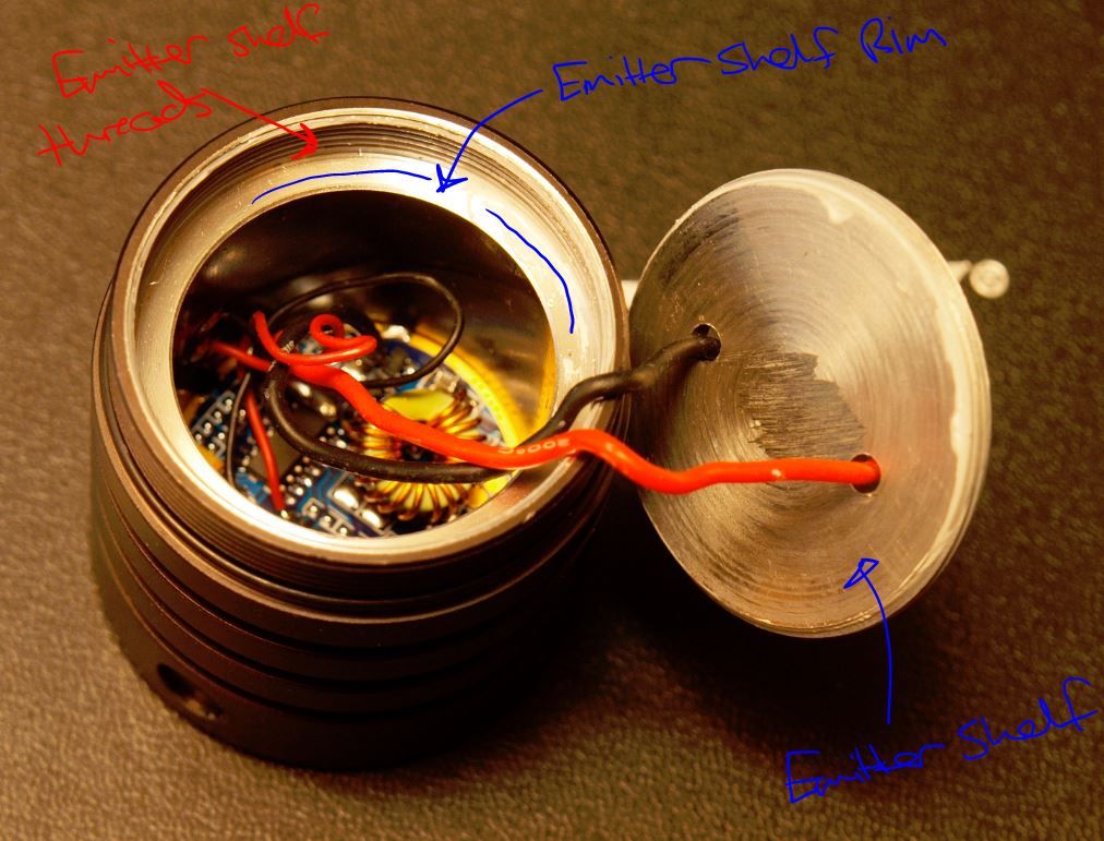
| top of emitter shelf from top of heatsink when in focus | ~2.7mm |
| thickness of emitter shelf | 3mm (3mm-0.85mm for pcb cutout) |
| - | |
| depth from top of driver board to emitter shelf rim | 27.5mm |
| depth from emitter shelf rim to electronic switch port | ~12mm |
| driver cavity inner diameter | 34mm (33.98mm) |
| - | |
| emitter shelf thread O/D | 41.75mm |
| I/D of emitter shelf threads in body | 41mm |
| depth of emitter shelf threads in body | 7mm |
| - | |
| thickness of driver board | 1.6mm |
| height of driver at highest component (including board) | ~12mm |
| - | |
| diameter of flat base section on reflector | 27mm |
So Rod, if you want to know exactly the distance between the bottom of the emitter shelf when it’s focused and the top of the driver board.
It’s…
distance from top of the driver board to emitter shelf rim (27.5mm) + depth of emitter shelf threads (7mm) - gap from top of threads when emitter shelf in focus (2.7mm) - thickness of emitter shelf itself (3mm).
And if I didn’t mess any of that up it comes out as 28.8mm, so your guesstimation was pretty damn close ![]()
If you’re wondering about the size of the copper slug you could fit in there though, you’d have to take into account the height of the toroid on the driver (around 11mm) and the electronic switch port which is only 12mm down from the edge of the emitter shelf rim.
-
Easiest heatsink enhancement I think would be a 34mm X ~13.5mm slug (copper/aluminium) lapped and bolted to the bottom of the emitter shelf. Then drilled to accomodate the two emitter wires.
Starting with a 35mm bar it should be fairly easy to sand the O/D down a bit and also remove the anodizing on the inside of the driver cavity walls (and open it up a bit as well) to get the combination close to being a press fit.
At least that’s what I’m going to be attempting I think, I have 35mm aluminium bar stock at hand and it should be doable without heavy machinery…I hope ![]()
Better would be to machine a whole new pill out of copper with threads and everything but that’s definitely out of my league, and I’m pretty sure a lathe is mandatory for something like that… ![]()
Many thanks for the info. I am hoping the heatsinks which I ordered from FT arrive within a couple of weeks. A copper slug of around 10mm in height might do the trick if I can find said slug in a hardware store.
Thinking out loud, the plan is to place the LED shelf upside down. With it upside down, the area where the LED is supposed to occupy, there will be a 20mm copper slug in its place. The surrounding area, I will place heatsinks which are 5mm in height. I will have to rely on the threads to transfer the heat collected to the body.
Also, with the shelf upside down, it should focus the LED better as suggested by janko.hrasko as it is sitting up closer to the reflector rather than the default position.
The problem with this approach is you’re not really doing much to improve the thermal path away from the shelf and to the outside. It will work well initially to suck and store heat from the led but the real weakness of the shelf is not really it’s thinness but that it can only transfer heat to the body through it’s small and loosely machined threads with minimal contact surface. Upside down or not the contact area is still pretty minimal and that will be the main bottleneck.
The idea with adding a 34mm slug that fits down into the driver cavity is that this will both collect and transfer the heat out along it’s own contact points to the driver cavity walls. Even if the press fit isn’t optimal you can increase/improve the contact area very easily with a few layers of copper or alu foil.
I’m pretty sure that will do a much better job at keeping the led cool than relying solely on those threads on the emitter shelf. You’ll see when you get the light, they’re pretty suboptimal…to put it kindly. :bigsmile:
Incidentally how easy/hard is it to remove anodizing on a specific part of a light without destroying the rest. Like could I paint on the degreaser/greased lightning only to the inside of the driver cavity and let it do it’s thing or would just sanding the coating off be a much better idea?
flipped shelf isn relying solely on those poor threads… it sits tightly on the rim and with some thermal paste there it isn’t that bad ![]()
sure copper pressed really tight would be better but I don’t think that it matters to me that much to have someone machine it for me
Hi Linus,
Thanks for the review.
Can you tell me what the outermost diameter of that heat sink plate the LED sits on is?
Sure, that’s what I’ve called the “emitter shelf thread O/D”, probably could have named it better. It’s 41.75mm.
I got tailcap lockout!
just unscrew the tailcap, unscrew the b- pcb, take it out
screw the three screws that were holding it to the body

place the pcb OVER the screws

get something that can create pressure on the pcb from the tailcap (I used a lid from film canister) and place it over the pcb

screw the tailcap on and BAM! ![]()
when you tighten the tailcap, it pushes the pcb on the screws and completes the circuit
loosen it a bit and the pressure from the springs breaks the contact
Nice and simple, good job! ![]()
Update: I ordered a custom firmware driver from DrJones (mokkadrv - 4 mode) that I’ll be using in this light.
Probably won’t do much work on it till I get this driver, too many projects on the go and I really need to get my BTU-MTG2 monster project finished up. ![]()
But I’m keen to see what others are coming up with in the meantime so feel free to post any progress or ideas in this thread so we can have a collection of useful info on this light.
If anyone has any questions or wants any measurements let me know, the light will stay disassembled for now.
Linus. I’ve just encountered the same type of threaded emitter plate on the Yupard I started working on. The COURUI has an integral ledge that the plate threads down onto, but mine doesn’t. I can’t add extra heat sinking that will transfer heat into a ledge that is part of the head.
Looks like the shelf threads in the body are also anodized on that Yupard, that can’t be helping thermal transfer surely.
I’ve got an idea! I’ll let you know if it pans out.
Allegedly, anodizing doesn't affect the thermal properties in a significant way. It might be measurable, but that doesn't mean much. If your wife says 'it's cold in here!' and you raise the temp from 63.4* to 63.8*, that's measurable, but probably not likely to do anything to stop the complaining. :)
A change in output of 1 lumen is measurable, but how much work would you be willing to invest for one lumen? How many lumens would an improvement have to be to be worth whatever work required to get it?
Just placed a order for 2 cant wait ![]()
Sure, I’m just suggesting something that could potentially improve a poor heatsinking solution.
I bet even small changes in thermal conductivity at the interface will have some effect when the contact surface from a loosely threaded emitter shelf is already minimal.
I don’t know how hard it is to remove anodizing though so it may not be worth the hassle, maybe the same benefit can be had by just slapping some thermal paste on the threads instead…
Removing the anodizing won't improve anything, as it's not a hindrance. It's not one of those little things that when combined with a bunch of other little things adds up to something meaningful, it just doesn't affect it one way or the other.
Now, an anodized outside surface has better radiative properties than bare aluminum, but for internal parts it doesn't matter.
I got my COURUI today. Eleven days. Wow! I really like the look and feel of this light. Now I have to decide what I’m going to do to it.
I’m getting a reading of .290A accross the tail on high. What am I doing wrong?
Did you remove the filament wire before taking the reading? ![]()
How’s the output of the light in general, you’d notice if that was the actual drive current. Would be very dim.