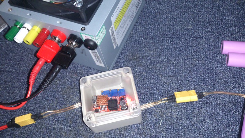
Finally got my board thrown together. I am using a 12 volt switching power supply that I had sitting in the closet, with magnet leads on the battery. Using Chinese banana plugs for the connections (I already had a bunch). I had an E09 tin sitting around that I wasn’t going to use for anything else that I decided would be a good candidate for a case.
Is it a flashlight?
Nope! Charger . I used some Fujik under the chip to secure it to the tin. It seems to be transferring some heat because the tin gets warm around the board. I put a little Kapton tape over the exposed metal on the board, just in case.
I soldered mine only on top and it works fine. I tested for continuity and they're the same node.
Also, in other news.
The charge indicator light is really quite simple and is absolutely no measure of voltage.
It states pretty specifically that the default is to switch off the LED after the current drops below to a multiple of the CC value.
I set mine to 0.01 of the CC value (I set my CC value to 1.499A - because I couldn't get exactly 1.5A)
My CV is set to 4.35V and my UR18650ZTAs as-is from FT settle above 4.34V.
Here is a pic of mine.
I power it using my modded PSU for my hobby charger.
I use XT-60s for connections and the battery holder is about to get replaced with a gutted charger with a slide that can fit protecteds and 26650s.
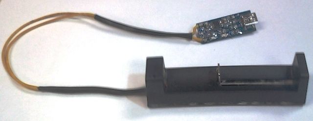
I like these cradles, I can solder everywhere so resistance is no issue. Just glued the circuit with a bit of hot glue on top.
The voltage pot seems indeed a bit touchy, or maybe my multimeter isn’t good enough for measuring hundredth of volt.
I accidentally connected a flat-top battery the wrong way because it was too dark and I was careless.
Lots of smoke and bad smells ensued. I saved the battery (only dropped down to 3.64V from 3.98V) and the next day I tested that the internal resistance was barely a few mOhms higher than the rest, so I charged it back up and it was fine.
I figured that a battery protection PCB wouldn't work properly if the battery itself polarity was reversed. Looked into some diodes, including shottkies and non-synchronous rectifying circuits, but they all were designed for the battery to be the only source and the protection only hand in mind the power coming from the battery.
So only circuit would be set at 4.29V, the other at 4.19V, the toggle switch would be on the input side of the charging circuit, and the circuit breaker on the battery side of the charger. Pics when done.
I can't take a picture of mine, because I fried the first one, but when it was functional, all I did was connect the in and out using the screw junctions and everything worked fine.
I'll get out my multimeter and check when I get the next one.
I Use these for my pink LG,s works very well I quick charge with my hobby charger first then finish with this little module.I parallel 4 batts at a time .
I don’t think those are SMBus. As you say, SMBus, which is based on I2C and can support multiple devices, uses one line for clock (SC), the other for data (SA). The lines on that PSU are labelled RXD & TXD, which looks more like a traditional bi-directional serial port.
Has anyone explored that power supply further? I think someone on Youtube mentioned that they couldn’t get anything interesting to happen with that connector.
I have one of those 10 A buck converters and that was my plan b for my project if i failed to pas 1 million cd with 4.2 volt. i was going to use 2x18650 in series and get whatever desired current to the led with using it. it looks a very decent driver this only that have to be careful with output range you set up otherwise i broke one xml t6 very easy with only 5v input. but i succeed in my project so i have this driver waiting for something else now
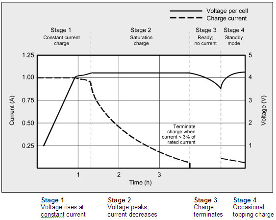
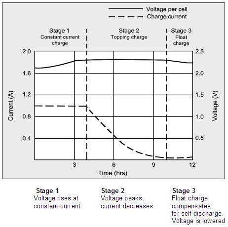
Charge pattern per cell in a Li Ion is almost identical to that of a properly charged lead acid battery (which just happens to have 6 cells in it
The current goes down on its own as the charging medium saturates (thus the full point being the current flow is not 10% of the battery capacity) , the constant current is there to limit MAXIMUM charge rate, otherwise just limiting voltage charging could be easily done with a constant voltage regulator, but the amount of current the battery will absorb initially will very large, dangerously large if not limited)
Notice the constant current dashed portion of the graph, voltages are different per cell naturally, but the constant current aspect is the charge pattern that determines the “fullness” of the battery
I use one of these to charge my daughters 6vdc lead acid battery in her little power wheels car, set to 2.35vdc per cell, then feed the output thru a HF multimeter, short the leads adjust max current rate to say 1A or less, then tie into the battery, you can watch the volts drop, current goes up…but after a while as the current draw lowers the voltage levels out at the set rate, then as the current decreases to around 10% of maximum rated mAh of the battery, then its full, nice thing is with lead acid you can set a float voltage or approx 2.25vdc per cell (13.8 for a 6 cell “12vdc lead acid battery” and leave it indefinitely as the battery no longer absorbs current at the lower voltage setting.
In fact if you charge at 4.2vdc, you can “float voltage” a Li Ion cell at 4.1vdc but the Li Ion chemistry and construction is very different and complex…it’s best to just charge then remove the charge from Li Ion where lead acid can be floated indefinitely
You can charge a 4.35vdc Li Ion cell on a 4.2vdc charger, it just won’t saturate fully, or ever maximum charge, it will be perfectly fine to use but won’t ever be at it’s full maximum mAh rating.
Manually charging a battery is possible…but it must be monitored CONSTANTLY, these Li Ion chargers the IC does the monitoring for us
They do offer Li Ion charging IC’s that charge at 4.35vdc…but you have to build the board yourself
Take this charger above, gut it, tie in the above linked charging module w/ a 4.35vdc MCP73834 (the MCP73833 is the 4.20fixed output chip) and it will charge those batteries at the correct CC/CV rate (also the Xtar MC1 is a good little host unit as well)