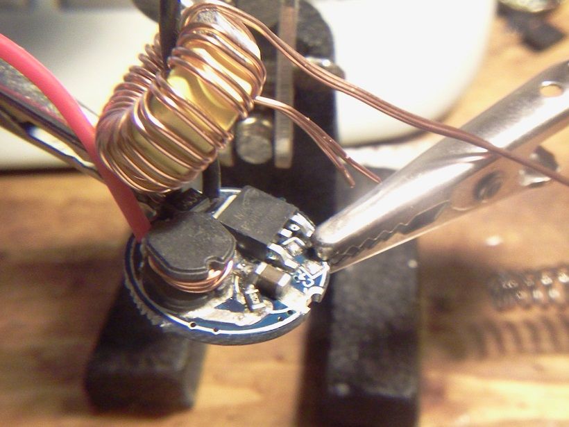
It appears to be the same driver as the KD super. But the led output side has a FET marked PHD45N03 LTA as seen in the pic.
http://www.lightmalls.com/super-output-ssc-p7-led-driver-board-low-high-middle-5-5v-15v-2
.
Its possible KD maybe shipping the same driver with the FET but haven’t updated the pics. :~
There was a lot of talk about similar drivers in another thread, that had to do with the current being higher with the larger toroid drivers, like the LCK-LED 5amp driver. As far as I can tell its the same driver with a different toroid and sense resistors as this driver in the OP, the lightmalls 3 amp driver.
.
I just happen to have a bare small toroid laying around that I had salvaged from something, I thought I’ll try that. So I set in and wired the toroid up with some wire and used about the same number of turns for the coil as the LCK-LED 5 amp driver. This is it setting on top of the original 3amp lightmalls driver.
.
.
This is the new coil on the right compared to the LCK-LED 5 amp coil on the left.
.

.
I then unsoldered the small toroid on the lightmalls driver.
.

.
Then I soldered on the larger toroid that I just made to the lightmalls 3amp driver and added the pot mod back to the sense resistors so I could turn the current up. Started with 2 laptop pulls Panasonic 2900mah cells with the pot turned to all it would do, going to a copper board MT-G2 on a Maglite heatsink with copper rod insert. The copper board was soldered directly to the mag heatsink.
.

.
I then tried 2 Samsung 20R’s, with the pot turned all it would do.
.

.
I then tried 3 2900mah cells.
.

.
I don’t have but 2 20R’s so I can’t try that. The funny thing about replacing the smaller toroid with a larger one like on the LCK-LED 5 amp version is that the FET never seemed to get hot like it did when I upped the current on the smaller toroid. Everything seemed normal as far as I could tell, but I did notice the pot was heating up quite a bit. Couldn’t run it to long because the MT-G2 was smoking hot on the Maglite heatsink. Needed to be mounted on a much larger chunk of aluminum.
So are these drivers the same with just different current sense resistors and a larger toroid, from what I seen, I believe so. All current readings are done with a MT-G2 so what could a XM-L2 do.
Thanks for sharing..
I have used one of the small 3A versions (small torroid) modded to 5A. So far so good. :)
Hi RaceR86, did you pot or heat sink the driver at all? Using the larger toroid did seem to make the FET run much cooler just by touch.
I got one of the last, maybe THE last, 4.5A version from IOS. Planning to do the same thing with it - MTG2 3D Mag, with MNKE 26650s (when I win the lottery).
When I keep looking around for drivers for a MT-G2 I keep getting those dead links to no longer available drivers at IOS. Why in the world did they quit selling them anyways.
Supposedly something about a new lineup of state of the art drivers in the works that will make the old ones obsolete... if it were anybody else I'd just laugh and shake my head, but Hank seems to be on a roll recently, so who knows.
I hope his got a real monster driver J) for a MT-G2 up his sleeve, I just can’t get over the amount of light they put out at over 7 or 8 amps or the heat either. I just don’t want to settle for anything less. I’m addicted. :Sp
Interesting. So, over-driving a 6V MT-G2 already resulted in early severe losses. Seems upgrading the inductor is the way to go from a performance/efficiency(?) standpoint.
I’ll get one of these in a nearby future, 3A version, to drive an XHP50. I’d like to step-up the current a bit, I have both 0’43Ω & 0’47Ω spare resistors lying around. Maybe I should also think on winding me up some sort of handy custom inductor made out of an old low voltage AC transformer’s windings. :innocent:
Well, I know the thread is pretty old but the driver is readily available (and good).
Cheers fellas ![]()
We like old threads around here.
Bummer. Just cancelled my “warm white 80+CRI” XHP50 order at Aliexpress, seller told me only “blow white” was available. ![]()
FastTech is stocking M2-7A XHP70 emitters, I’m waiting for their feedback to know if they are 80+CRI units .
Does someone have this driver at hand? Are these current feedback resistors of 1210 imperial units size?
Cheers
Well, I published a thread on this product’s page at FastTech a week ago, and about a little while I’ve expanded it with my findings:
Information on current delivery modifications and efficiency
Briefing: three 1210 ½W three ¼W 1206 0’2Ω sense resistors are onboard, total combined shunt resistance is 0’06͡7Ω, sense voltage is 200mV.
Cheers
Well, going to get a unit of this stuff finally, aiming at around 4’2-4’8A of current delivery. Good to see these toroidal inductors, cos I’ll end up custom tailoring one for my driver. Hope it’s not too hard to desolder the onboard one. Thanks fellows.
Cheers :partying_face:
No hot air reflow? I’ve found sliding the part off can overcome the surface tension that resists pulling straight up. I’m curious about the outcome but these are still 19mm drivers and don’t fit most of my applications.
No, unfortunately just basic equipment here. Helping hands, a heavy duty 26W JBC 30N soldering iron, etc and hints and tips.
Since I can do away with the stock inductor, I may heat up the whole wire pack thing and that’s about it.
Cheers :partying_face:
Clamping it to a damp rag migh be enough to prevent parts from coming off the backside since you are heating the biggest component on the board.
I have this in the mail: Cree XHP70 M4 40H 4000K Neutral White LED - 1 Piece plus a “Nichia 219B”.
Aiming for 4’2/4’8A of output.
The 219B is for a 3-mode SK68 clone mod.
Cheers :partying_face:
Barkuti,
How do know if your inductor is the right sized prior to installation? Do you test it or make an educated assumption? Do the ferrite cores vary in composition or can you wrap any ferrite core? I save all of the bits and pieces of everything I tear apart. I could easily re-wind an inductor but have no clue on the theory side of things.

PS, Nice necro post.
Well, I'll probably make an inductor out of an old school AC/DC brickwalwart's transformer secondary windings. I have a 230VAC/9VDC transformer (edited: this one is a keeper, using it to power up the kitchen scale you can see some messages below), a multi-DC output 220VAC/(12/9/6)VAC transformer too, and a rare and chunky 230V/35V unit. I'm gonna put a 9V cell in my used kitchen scale to see how much it wheighs. ;)
Cheers ^:)
P.S.: fixes and updates here & there (2016/05/0, 07:17).
Ooops!
With respect to the size, my plan is to make it at least big enough to output 4’8A of current without much effort so, if make it a bit smaller than this thread’s example replacement, it should handle 5+A well.
Cheers :partying_face:
P.S.: I should not afford more than 10mm driver board height, or else I’ll have to chop a bit the baseplate’s internal pill support heatsink, LOL!