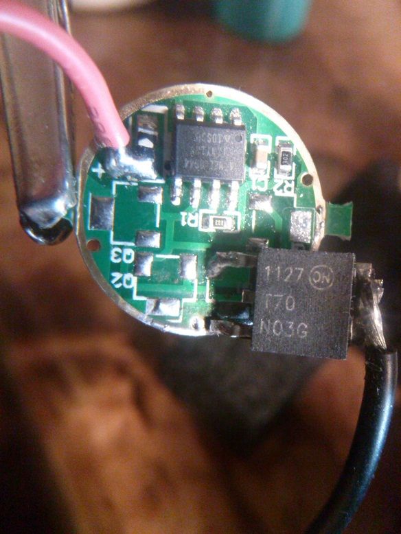
Red 'JB' driver, 70N02, toroid, MiniMo PWM=1

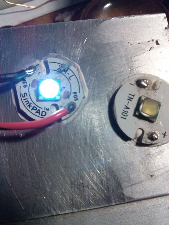
Werner's 098b (PWM=7), toroid, 2SK4212 FET, left; MiniMo (PWM=1), NO toroid, same 2SK4212 FET, right:

Much shorter exposure on the second pic, the background lighting was the same for both pics.
Red 'JB' driver, 70N02, toroid, MiniMo PWM=1
Werner's 098b (PWM=7), toroid, 2SK4212 FET, left; MiniMo (PWM=1), NO toroid, same 2SK4212 FET, right:
Much shorter exposure on the second pic, the background lighting was the same for both pics.
the geek speak hurts me wee head. I beg of ye, please create a how to/info post on this thread, explaining in everything in plain engrish so us mere mortals can understand.
I have no idea what you have done, but if it makes an srk usable, and is budget-ish, I will take a hundred of ’em
The microcontroller, whatever it is, on the SRK-style drivers isn't reflashable, at least not by us. I'm sure somebody somewhere can do it, but I don't even know what the chip is.
The stock modes & UI suck. We can write and flash out own programs for the chip used on the Nanjg drivers, the attiny13a. This is just using a Nanjg driver's controller to run the driver hardware on the SRK-style drivers, with code that works better than stock.
Strip off all the 7135s from a Nanjg 105c, feed it power & ground like normal, then run a jumper wire from the 105c's PWM line that used to run the 7135s over to the spot on the SRK driver. The 105c's brain never knows anything has changed and just does what it's programmed to do. The SRK's driver controls the current to the LEDs, and it never knows it has been given a different, alien brain.
Werner's firmware is: Short press ascends from low to high, five levels (and one level at 0%, which is 'off'). Only turns off by cycling back around to the 0% level. But, a long press descends through the mode order, from high to low. So, with the light off, a short press followed by a long press, turns on in the lowest mode, and then turns off. And a long press followed by a short press turns on in high, and then turns off.
DrJones' MiniMo is similar but has a long press for on/off, and a short press ascends from low to high. Has memory so it comes on at the level last used.
Thanks comfychair. I could understand your last post. It makes more sense now. ![]()
I’m beginning to think that toroid with short spikes of power due to the PWM makes the ckt act like a joule thief…charges the toroid field, as it collapses it pushes the energy it built right back down the line, longer PWM cycles don’t let the field collapse and it just shoves the power thru it

Ok comfychair, I tried it out, if understand correctly what your doing. I used a stripped down version of a old DX 7612 board. Mainly because I wasn’t using it and all the amc7135’s had been removed for something else. I used the T70N03 FET, a little soldering and added some wire and presto.
.
.
A direct drive driver using a attiny13v with Dr.jones code and nothing removed but the amc7135’s. Changed the modes to 1,2,3,4,5,15,78,255 for testing purposes. It lights up even in the low pwm value of 1. That’s a pretty awesome moonlight mode. High mode yeilded 4.5 amps of draw from a single 20r. I may strip my 4 board amc7135 2800ma kung and try the direct drive method. All modes worked reliable and perfect.
Flip the FET over and bend the legs so they're a mirror image of stock, glue it to the PCB with epoxy, then solder the legs. Voila - a super-East092! You can also trim off the overhanging part of the tab and file down the corner that sticks out to get it to fit in a 17mm pill.
{0,1,3,8,20,50,120,255} is really nice with a FET (doesn't work so great if still using the 7135s).
The (pwm value 1) moonlight mode is just a faint glow, the die turns from yellow to white. Its nice to 4.5 amps on the high end and still have a very faint glow on the low end. Really when driving a single xml or xml2 around the battery direct drive current, there’s no need for the amc7135’s, their not doing a thing.
Is there any particular reason why 0,1,3,8,20,50,120,255, is such low on the low end, would starting at 0,3,5,7,9,20,50,255 be better, at least have the light start with a little oomph, or since it's so low it's for reading or something like that
I understand what the 0 thru 255 is for the binary equivalent of all 0's all the way up thru all 1's...pretty nifty (I guess some way to calculate the on/off time of the cycles)
I guess I will have to build me one to see, then figure out how to program the ATTiny13A
I can’t seem to manage to get a picture of pwm value 1 that actually represents what I’am seeing.
@WarHawk-AVG I use moonlight mode with my EDC light more than any other mode, while everyone else in the house is a sleep. I can see just enough to get around without disturbing anyone.
This still doesn't hardly represent what I'am seeing, but its the best i can do. You can actually see only the die lite up white in a square shape. You can even see the bonding wires without being blinded. Pic is with pwm value of 1, Mouse over for pwm value of 5. Five is the lowest I have been able to run the amc's at stable.
Try it with the flash on.
comfychair, why don’t you just transplant the microcontroller?
That’s what he actually does, but the footprints of the Controllers Are Not the Same.
So he uses the nanjg as a mothership, also the nanjg has a voltage divider for the battery protection and a reverse voltage diode on board…
aah… all is clear now. thanks
Edit: by footprint do you mean pinout?
reedit: answered my own question: different pinouts.
Yeah the controller on those big FET boards ain’t a ATTiny13A like on the 105c, so he uses a stripped 105C as the brains to control the FET, it’s actually incredibly simple and effective other than having to use another “daughter” board, kind of like a shield plugged into an arduino…but in reverse
Thanks RD, Ill try that next time, I already tore it down to install in the 4x kung.
Both pics where taken with a desk lamp pointed straight towards the led, that’s the only way I could get the pics from being a light ball glare. Its still not as faint as I see it.
SRK driver swapped into the last 'Securitylng' light that was still using the stock driver/MCU...

Running Werner's 098b, PWM=7 on the left (3-toroid SRK driver), MiniMo PWM=1 on the right (JB driver with added single toroid):

With this FET option, it sounds like 4.5A is the best it can do with an XM-L2 on copper (used a Sam 20R)? This sounds a bit too low - yes, I'm a amp nut. But for example in a pretty decent well heat sinked host, like a HD2010 or XINTD X3, I would like to push it above 5A, and would expect direct drive to have lower resistance than a pile of 7135's?
My meter, my battery box, my test leads, my LED, and so on... your stuff may give different numbers. But if it only increases by 0.1A when the FET is removed from the circuit, it's an excellent FET for single cell voltages.