Is there any particular reason why 0,1,3,8,20,50,120,255, is such low on the low end, would starting at 0,3,5,7,9,20,50,255 be better, at least have the light start with a little oomph, or since it's so low it's for reading or something like that
I understand what the 0 thru 255 is for the binary equivalent of all 0's all the way up thru all 1's...pretty nifty (I guess some way to calculate the on/off time of the cycles)
I guess I will have to build me one to see, then figure out how to program the ATTiny13A
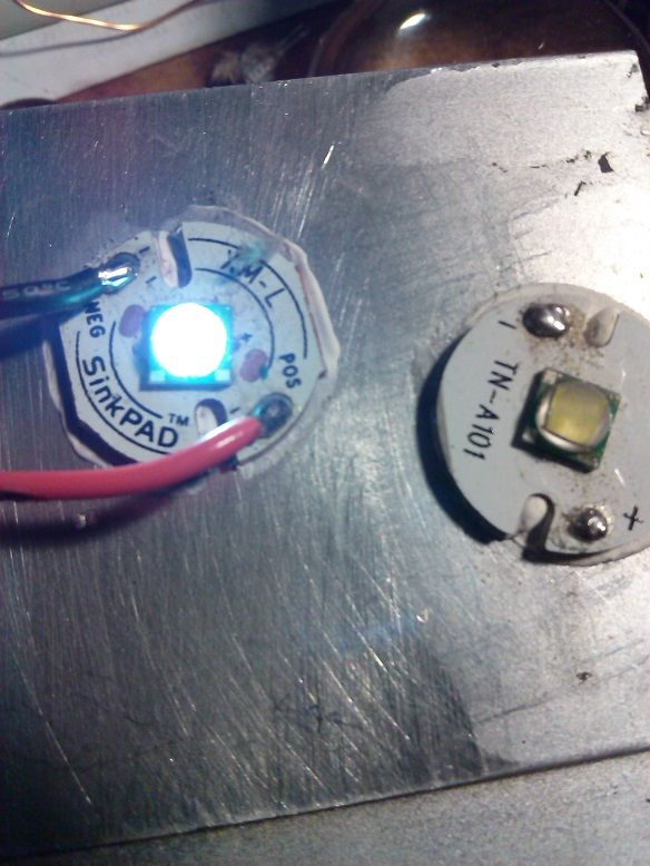
I can’t seem to manage to get a picture of pwm value 1 that actually represents what I’am seeing.
@WarHawk-AVG I use moonlight mode with my EDC light more than any other mode, while everyone else in the house is a sleep. I can see just enough to get around without disturbing anyone.
This still doesn't hardly represent what I'am seeing, but its the best i can do. You can actually see only the die lite up white in a square shape. You can even see the bonding wires without being blinded. Pic is with pwm value of 1, Mouse over for pwm value of 5. Five is the lowest I have been able to run the amc's at stable.
That’s what he actually does, but the footprints of the Controllers Are Not the Same.
So he uses the nanjg as a mothership, also the nanjg has a voltage divider for the battery protection and a reverse voltage diode on board…
Yeah the controller on those big FET boards ain’t a ATTiny13A like on the 105c, so he uses a stripped 105C as the brains to control the FET, it’s actually incredibly simple and effective other than having to use another “daughter” board, kind of like a shield plugged into an arduino…but in reverse
Thanks RD, Ill try that next time, I already tore it down to install in the 4x kung.
Both pics where taken with a desk lamp pointed straight towards the led, that’s the only way I could get the pics from being a light ball glare. Its still not as faint as I see it.
With this FET option, it sounds like 4.5A is the best it can do with an XM-L2 on copper (used a Sam 20R)? This sounds a bit too low - yes, I'm a amp nut. But for example in a pretty decent well heat sinked host, like a HD2010 or XINTD X3, I would like to push it above 5A, and would expect direct drive to have lower resistance than a pile of 7135's?
My meter, my battery box, my test leads, my LED, and so on... your stuff may give different numbers. But if it only increases by 0.1A when the FET is removed from the circuit, it's an excellent FET for single cell voltages.
Switch wires are connected to the underside (black+red twisted, you can see them heading off to the left out of frame) so as to not block access to the MCU pins for reflashing.
Ah, good idea. I think I had mine hook to one of the stars, seems like it was the last one on the right.
I guess it depends on which one is used in the code. I’ll have to go back and get a little refresher coarse in how to make lower modes, the one I have only goes to pwm 5 and it has a few more lines that reference that value.
.
One more thing comfychair, have you looked at your joined date and your post count. Wow!
Yes I have used this on my M6 that’s how I came to the idea of using a nanjg as mothership.
I have stripped the original mcu and there was a special mode order necessary because the 7136 behave a bit different than a plain FET.
I guess you could try to use it with the stock mcu still in place like comfy first did, but I don’t recommend it for longer use because the standby current of the original driver is quite high….
Another one, this time with the stock resistors still functional.
Remove the stock controller, optionally place it on the floor and smash it with a hammer for proper disposal.
These are the 3 pins that go to the 3 gate drivers that go to the 2 buck controllers that run the 3 FETs. What an elegant design! :Sp
OCD? What's that?
See? Now they're mounted properly.
While still hot, smoosh the heatshrink down flat. Holds the wires in place tight enough that no epoxy is needed.
Power for the brain is picked up from the inboard tab on the big yellow capacitor (the cap's outboard tab goes to ground). The brain's ground comes via the copper mounting frame. The single black wire connected to the big driver's three PWM pins goes to any of the 105c pads that used to control the 7135s.
The only thing left to do is attach two pins to the back of the switch PCB, and corresponding female connectors to the ends of the switch cable. Makes disassembly so much nicer when you don't have to futz around with that stupid switch bezel just to remove the driver.
I measured L1=2.48A, L2=2.47A, L3=2.35A. All 3 channels have different resistor combos because of the vastly different PCB traces, but odd that the low one only has a single R010 resistor, while L1 has a R010 & R110, and L2 has a R010 & R068. Every one I've seen of this style has those same resistor values in the same locations, but I guess that's pretty close for a $5 driver.