I’m using an S3 Convoy for the build. I used a pre-1980’s penny as those are copper. To get it to fit the pill I had to shrink it down. I thought about cutting it and figured it would not go well, so I tried to imagine what Match or OL would do. So I figured on drilling a hole to mount the penny on a Dremel grinding wheel thingy…
Trimmed now ready for some lapping.
Fits good. More loose than I wanted. Meh.
Now for solder, I’ll use the scottyhazzard reflow station.
More lapping to do but shaping up…
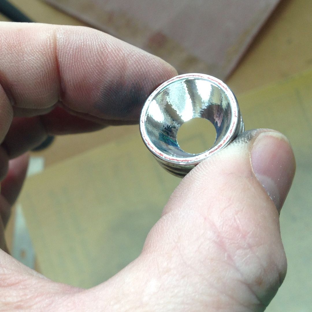
The hole for the LED is too narrow so I sanded, ground, lapped and polished the reflector until it fit over the large emitter of the MTG2.
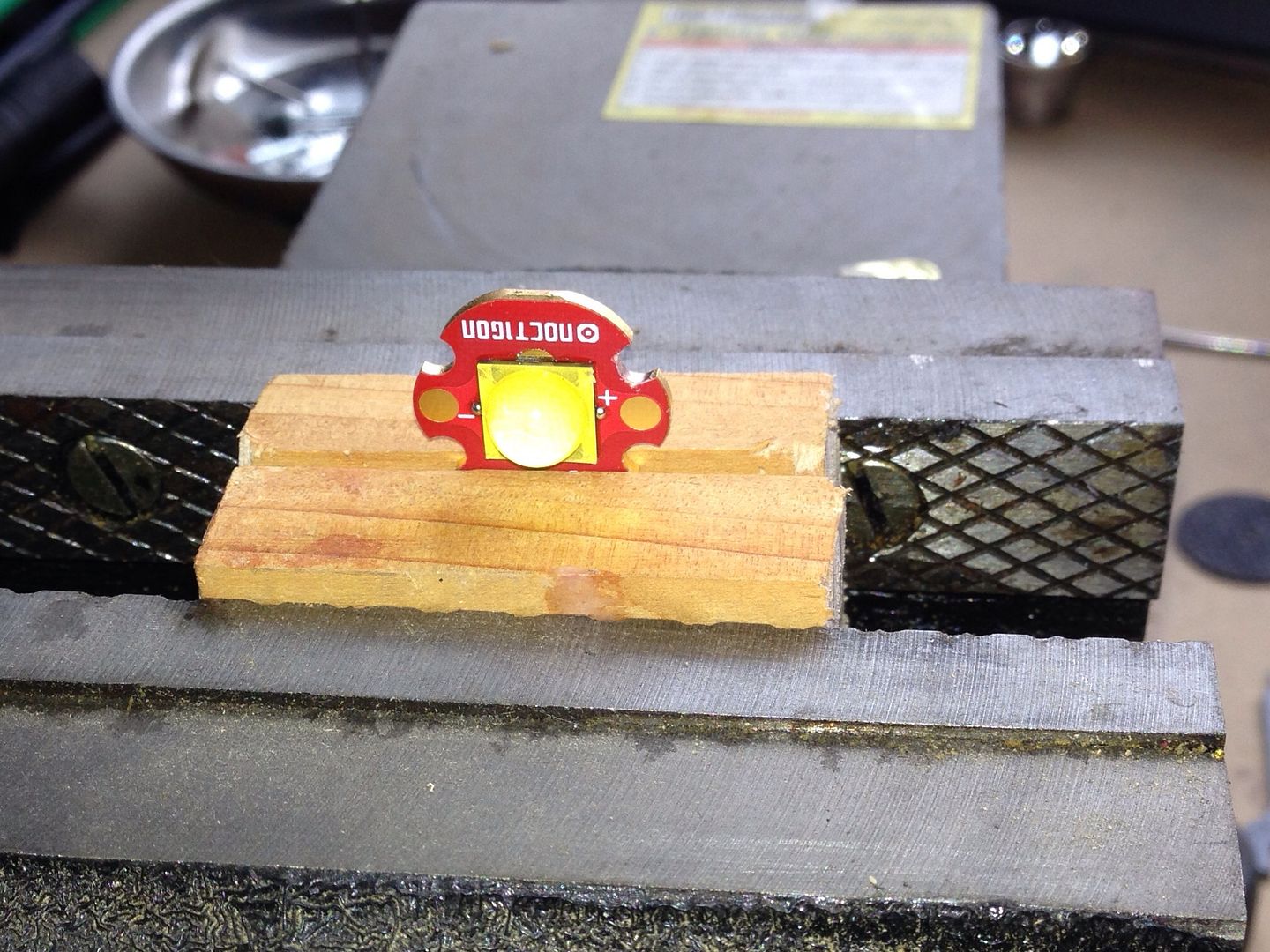
That’s where I was at before going to work. Tomorrow I plan to do a test fit, I might need to put another slice of copper between the MCPCB and the pill. Once the hight is good then I’ll drill some holes for wires and some screws to hold it together. If that all goes as planned then I’ll solder it up and see what happens.
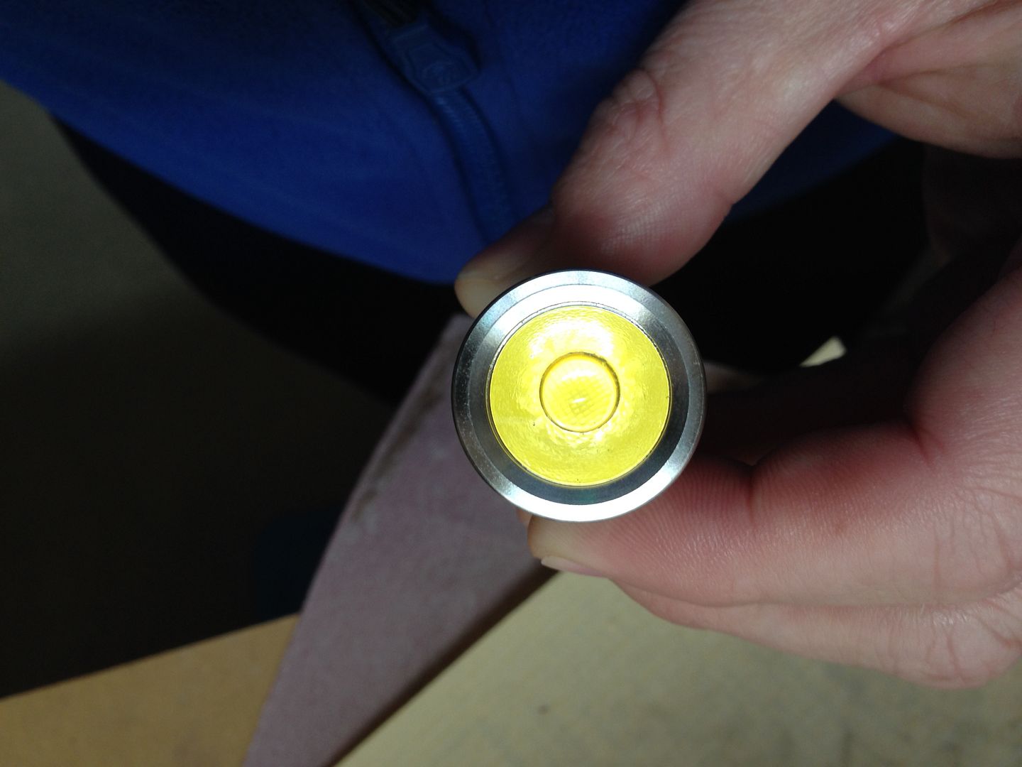
Fits together nice…
First hiccup. The holes are too close together and don’t communicate through the star
So I’m trying to create access, grinding on the star makes me nervous…
So I’m grinding grooves into the pill and my batteries die. (I just remembered what I was going to do before going to bed) D’oh!
Well done scottyhazzard. Looks like something OL would do.
Great job, looking forward to seeing the rest of this build.
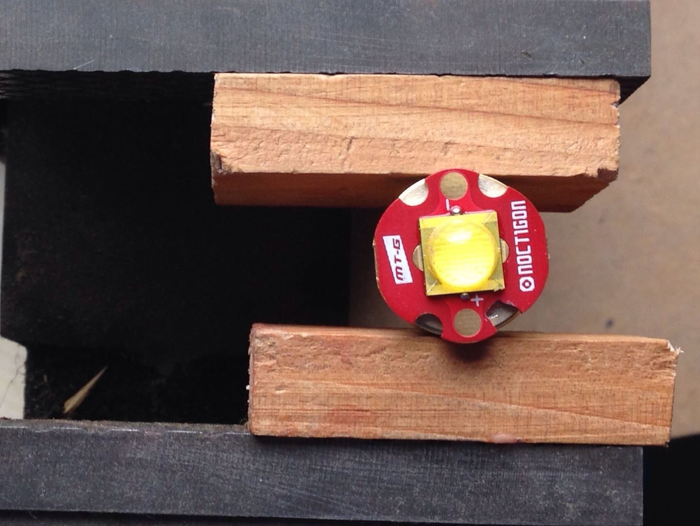
The MT-G2 is a monster when driven well.
Nice work, good idea with the penny and how you trimmed it…nicely done!
MT-G2, look left at my avatar. Comfy and Richard and a couple of others have been working on something intriquing. They are removing all the chips from a Qlite or 105c driver and putting an FET on the board. Just one. It lets the emitter pull almost direct drive current from the cells. Wanna know how this works with the MT-G2? I just put one in my M8 today (Thanks Richard!), tested a lot of different cells. It works FABULOUSLY! Want to control how hot you run it? Use a lesser cell, want to run it to the max, use a 20R or Efest 35A. I’m pulling 10.51A and making 4244 OTF at start-up, 3547 OTF at 30 seconds. And oh yeah, moon mode on an MT-G2, how’s 7 lumens sound? It’s insane, loving it!
Looking good, keep up the good work and keep the pictures coming!
For the record, $1.08 apiece Sanyo UR18650FJ lap pulls do 5.82A and 2853 Out the Front at 30 seconds. Not shabby at all! With 5 modes I have 7, 55, 414, 1998, and 3547 lumens on demand. (with a pr. of 20R’s)
Edit: Even in a chopped AA MiniMag running from 2 IMR14250 cells on a “stock” Qlite, the MT-G2 will do 1346 lumens in mule mode (no reflector) In a small light, beware that it does indeed make a lot of heat, over 3A it grows exponentially.
Thanks guys. I’m really enjoying this. In fact I just worked on it some as soon as I got home. Still in scrubs, stethoscope in my pocket drilling into the copper I added to the pill. Something must be wrong… it appears to fit perfectly. Mind you the driver has not had the thick silicone wires soldered or been tacked to the pill with solder, just tested to see that it fits together nicely. Hopefully the reflector won’t ground out as I have no kapton tape. I dread having to go to Fry’s for kapton but I’ll cross that bridge if I have to.
DBCstm, your talking my language. Are you able to get high medium and low modes? The last that I heard there were issues with PWM and whining. I gotta get more copper. My next project is a triple XML and I was hoping to use that driver. I’m stoked it’s working for you.
I will update with more pics tomorrow. Thanks guys.
I posted the lumens for each level on the M8 with the FET driver in the thread up above, the Qlite in the chopped AA is running the standard Low-Med-High. No whining, no flickering, just works.
Itinifni, I have been looking at copper slugs, washers, wire, sheets and shaped punch outs on that Etsy… I was just impatient and wanted to see what I could do now. They have a great selection of stuff like these would be cool on top of a braided spring. I think all my discretionary money will be going to Richard’s Mountain Electronics and Etsy.
Great idea Scotty with the penny. I filed a few down the other night, along with a couple of old aluminum stars.
Now that I’ve seen your idea for shaping them down I sure feel like I’ve wasted some time. Thanks for posting and look forward to seeing your completed build.
Um, y’all do realize don’t you that destroying pennies is a Federal offense? If ya just gotta do it, perhaps you shouldn’t proclaim it on a public forum.
Copper sheet is readily available. There are punched copper discs to be found on ebay, even the cheap copper stars that have a mask under the thermal pad are useful for projects such as these. Government monies are wasted badly enough already…
And I’d only drill a hole to mount the disc if I was planning a triple that had a hole in the center of the star. Otherwise, you’ve removed precious heat sink material from directly under the source…the emitter. There was an article about the path of the heat under the emitter, accompanied by spectrograph charts, that showed the heat tends to take a similar angle as the beam of light itself. So the area directly under the emitter is crucial.
Would love to see these tests. We’re the emitters on stars with big heatsinks sucking the heat down? Is there any way to direct this heat outward towards the body?
If you draw a V that represents the radiant angle of the light coming out the front, extend the arms of the V down into an X and that’s kind of what the heat dispersal looks like under the emitter. The only real way to get the heat to disperse is to bottleneck it, making it spread out, much like blocking the light with a reflector to guide it. BUT, in so doing the path of heat dispersal is also slowed, causing the emitter to run hotter and thereby less efficiently. Heat is going to be radiant by it’s very nature, so giving it good contact will automatically result in it filling up all the sink material available, with ambient temperture being a key factor in removal from the surface. This is where the fins come into play. Are the fins adjacent to, above, or below the heat source? Would seem to me that fins below the heat source would be more of a sponge, wicking heat from the source to the outside air. Fins above the source are only going to come into play when everything is saturated and effectively backing up to the fins. Adjacent would be a compromise between those two factors.
I’m no engineer, just someone that’s been burned. lol I’ve worked outdoors in the Texas sun most of my life, radiant heat is a way of life. You DO NOT lean your forearms on a dark rusty metal gate in full Texas sun in August! Or the blue hood of a car. Or the dark green plastic slide some idiot put in the playground for my kid to play on. For me, it’s like running a water hose over a slanted sheet of plywood, the water will run straight down and leave the board if nothing stops it, put a deterrent in the way and the board will get wet on a wider path. Similarly, let the heat escape and it will take a straight path out. Block it, and it will back up and saturate everything. Right? So, getting a direct thermal path under the emitter and enough sink mass to radiate the heat out to the fins for the air to take away, and there’s your efficiency. Simple enough on the face value, more difficult than that in application. So now I can be shot down with all my ideas.
Run an MT-G2 at 10.5 - 12 A and see where the heat goes…
Speaking of heat… #%$&, I destroyed my driver in a pathetic series of soldering whoopsies and and hurried shoddy repairs. I was so excited and so close I just knew I could make the repairs and get it to work. There goes $20. Will be placing an order with Richard tomorrow. I can salvage the chips to use on another build using reflow. I can do reflow but the soldering is still a work in progress. So a little break until more parts arrive.