Definitely interested in a couple of these if you offer them for sale here. ![]()
Plus it’s less stressful on the LED
interesting.
Everything is the most awesome thing ever, sorry to have rained on anyone's parade.
Low modes are simulations of low current output but with high Vf issues.
I don’t want to fan any flames here but I don’t understand this statement. Can someone put it in layman’s terms for me?
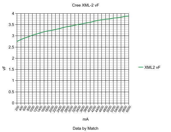
20% with a 5A output driver using PWM will do 5 amps for 20% of the time, and 0 amps for 80% of the time. The Vf required to get 5 amps through a XML2 is 3.75-3.80A. Tailcap amps will be a measure the average current, around 1A.
But, a non-PWM constant 1 amp into the same LED only needs an output voltage of 3.05-3.10 volts.
How preliminary is this preliminary? 2 weeks off or 2 months?
Do you have an approximate price range?
Can you expand on how the user can change the modes? IE programmed through the switches or through hardware programmer like the Atmel chips?
BTW: SOOO COOOL! :-D Looking forward to seeing more of these. A lot more!
Yeah CC, That’s the efficiency part. The stress part is that just about any component will wear out more quickly from excessive switching and power usage beyond design parameters and pwm can do both. While we generally don’t worry too much about over taxing our poor LEDs, surviving abuse isn’t the same thing as not being abused and if this driver gets the job done without as much wear we get the power and run time together while not doing as much harm to the emitter or other components. Not a concern for everyone but certainly worth understanding.
Answers to questions:
-yes,I will send one to HKJ,and there will be probably giveaway(4-5 drivers) because I want some input and opinions.
-current can be increased or decreased by changing sense resistor,max. current is limited by max. power dissipation(heat) on power mosfet,and that depends a lot on led Vf,battery voltage,how good is thermal contact between driver and flashlight,but this driver is designed for single xp-g2,xm-l2 so 5A is more than enough because of high Vf
-theoretically it is possible to add "external" mosfet and stack sense resistor for 9-10A current,but this should be tested in reality(and you loose overtemp protection this way)
-as for 2S (8.4V) capability I'll see what can I do,I want to preserve low voltage warning/protection(I assume for MT-G?)
-no mode changes via switch(es)-I really don't like "menu" idea when you have only one button(equivalent is writing this text with only one button),and when you have side e-switch capability in firmware at the same time,there is a good possibility for chaos.
Keep it simple as possible was main guideline during both hardware and firmware part developing
There are 2 "stars" with 4 possible mode groups,enough for 95% of people,but if you want some different modes,I can do that(free of charge for simple mode changes).What will be those 4 mode groups depend on BLFers,the most wanted groups will be in production version
-as for turbo mode:Is not that simple to explain(turbo is not constant because of some hardware limitations),but something like this: ~140% when input voltage is 4.2V and that drops linearly to ~110% when input voltage is 2.8V-in practice this doesn't matter because max. possible current is smaller anyway as battery voltage drops
Some additional info:
-uC is PIC,not Amtel
-moonlight mode in this version isn't possible because of hardware limitations; 10mohm sense resistor and 5mA moonlight current mean 0.01*0.005=50uV sense voltage!
That's disadvantage of PWM-less constant current topology.Auto zero opamp would solve this,but prices of those are considerably higher.So maybe I'll offer moonlight version at higher price.
Runtime-efficiency explanation
It's a known fact that all leds have higher efficiency(lm/Watt) at lower forward currents.For example XM-L2 U2 has98.7lm/W@3A, 140.6lm/W@1A nad 170,7lm/w@0,15A (no data for low currents,but one can expect close to 180-200lm/W at very low currents).
In case of PWM based drivers,LED efficiency on all modes is the same and equal to efficiency at highest mode.This is because led current is always the same as on highest mode (3Amp for example),but PWM driver turn led on-off fast compared to eye response so we see "average brightenss".Multimeter also sees average current but if you check current with oscillocope you will see pulses of 3Amp current.
In case of PWM-less CC driver,I(t)=average current,there are no pulses,so LED efficiency depends on current-the lower the current,the higher efficiency.
You can see difference in LED efficiency for XM-L2 U2 at 3Amp max. mode in this table:
|
3Amp |
1Amp |
0,15Amp |
0,03Amp |
PWM CC driver LED efficiency |
98.7 |
98.7 |
98.7 |
98.7 |
PWM-less CC driver LED efficiency |
98.7 |
140.6 |
170.7 |
~190? |
The higher the "high" and lower the "low",the more extreme difference in efficiencies between those two types of drivers.
This means two things: you could get more brightness at same average current-same runtime,or you could reduce current to get equal PWM CC driver brightness-longer runtime.
For example: 1% low mode for PWM-less CC driver would be just as bright as 2% low mode PWM CC driver.That simply means current drain from battery is reduced by half->and that means two times longer runtime on low.
Regulation vs. time explanation
In case of PWM based drivers, Vf on lower modes is the same as on highest mode,voltage sag is the same on all flashlight parts as on highest mode!
Check HKJs graphs for 7135 based drivers,on lower modes,current is constant until battery voltage drops to ~3.4V,same as on high mode,no matter what mode you choose.
Voltage drops at springs,switch,wires remain the same on every mode.
In case of non PWM CC driver,on lower modes current will remain constant until battery voltage become lower than Vf of LED at that current,for example 3.0V@300mA. Also there will be less stress on battery,springs,led die etc.
My next plans are:
-order small quantity of pre-production (last and final revision,I hope so) versions of pcbs
-finish software part-polishing+add mode groups and switch styles that are useful for most of members
-assemble drivers and send some of them to HKJ,RMM,and organize giveaway for BLFers
-will see what after that
I think for MT-G2 is no low voltage warning needed, because of the 6V (or more) Vf! The lumens will drop dramatically when 3v per cell is reached.
I’m very interested, can’t wait for the final version! I’d probably buy several.
You have a good plan, stick with it. I won’t miss moon mode but lowest feasible low is likely a must. Start low and go up or start high and go down, 4 each. High, low, strobe, SOS, and slow beacon(diving). Low, high, mix of strobes(for cycling). Definitely in for these as it looks like a BLF tailored 17mm version of an LFlex only better. Hard to imagine it being cheap but at $18-$25 you might sell some. $10-$18 a lot more. LFlex is $25.
I would say >$15 including CONUS shipping. ![]()
Price predictions are guesswork as it is so dependant on volume.
But a guess from me would put it in the 12,5-15,5 USD for 1 and then dropping to ~10,5 for any number above 5 but below 50.
And I have nothing to back that up at all. Basicaally just hoping the price will not be so high that it is out of my range.
BTW: There is no voltage boosting going on here right? Right? So it will be really hard to reach the 5 amps on XP-G2 for anything more than the first few minutes due to the Vf issue same as when direct driving them?
I guess what I am asking is whether the limiting factor will still be battery quality and voltage as there is no mention of boost ability so far?
1/4 mile dragsters have small tanks, long haul trucks have big ones. How long you can maintain full power depends on heat sinking and the cells.
Just curious… Would adding a capacitor at the LED help the PWM be more efficient?
Thanks comfychair. I can understand led4power’s efficiency graph as well now.
Nice design! I hope all goes well with your final wrap-ups. Of course I'd rather see this go open design, open source, but hopefully this way, it will have a better chance to make it. The PIC controllers are pretty powerful. I believe there's been custom drivers developed using it, though maybe never made it to distribution. For $15-$20, I would guess it's gonna be tough to sell in quantity, considering most of our single cell lights are $10-$20 now, some to $30. To me, it would have to be under $10, and if more, I would buy/use very limited #'s.
Ideally, if you could hook up with a real manufacturer to get some production volume, then be able to pass along that qty savings to the us hobbyists, that would be really nice! Even if it's semi-custom manufacturing -- there are those guys out there who would probably be interested.
First let me start off by saying that I know very little about the specifics of this kind of stuff. Just enough to get myself in trouble!
Isn’t a constant current driver, based on a mosfet, that doesn’t use PWM, simply a linear driver? Unless the mosfet is in the full ON state, while operating in lower modes, isn’t all the extra power (voltage) wasted as heat?
If so, wouldn’t the efficiency benefits of driving an emitter with PWM-less constant current, be negated by the linear current controller wasting the extra voltage as heat?
I understand that an LED runs more efficiently with a constant current at lower amps, then pulsed current at higher amps, but pulsed current doesn’t waste any energy as heat, while a linear constant current wastes all extra voltage as heat?
If all this is correct, even with the energy loss through heat, is a CC linear mosfet driver still more efficient than the same exact mosfet driven fully on/off with PWM used to control current?
I’m not simply talking about whether the LED is running more efficient, because it will, but I’m talking about battery life, and current actually drawn from the battery?
This probably won't go open source,but if(when) I make a deal with RMM,I'll get him full access to firmware so he can change modes and other stuff for his customers.
Yes,it would be nice if all things would be free,open source,but every time when you make-design-create something and spend dozens-hundreds-thousands hours/dollars,you have more respect to other's creations/designs.Not to mention years of learning and thousands of "place a currency" spent on education/college.If everything would be free,no one would do anything,because why spend money/time/effort if all you'll get is "thanks,you're da man"?You can't live from thanks'.
Free,open source stuff is usually something simpler,or created by a "X" of people,and every of them invested "1/X" of his time-money-effort (1 person should invest "X" time-money-effort to equal that).
Mosfet is in linear mode which is equal to "smart" resistor,so yes there will be dissipation Pd=(Ubatt-Uparasitic-Uled)*I.
But in PWM CC driver that heat is also dissipated,but somewhere else- internal battery resistance,springs,wires,tiny gold led wires,internal led die resistance.
What do you think which is better/worse?
Extra voltage must be dissipated somewhere in lin. drivers,no matter PWM or PWM-less. And because main battery parameter for lin. drivers is capacity [mAh],driver that causes better LED efficiency (consumes less current for same brightness) will power led for longer time.