It comes with no battery at all. But I guess if you put 3000 mAh cell of quality brand you will get similar runtime to the RAV power (If the later indeed has 3000 mAh battery inside)
I’ve been cycling one with the top off. As indicated in the review the LED’s are OK when charging but woefully dim when discharging. I can barely see them with the top off….in the dark. Actual charge performance seems OK. Using with laptop pulls.
I have not tried putting the lid on/off yet. I have an identical appearing one I purchased a couple months ago with a battery already installed. The lid is a tad tricky to get off but does if you work it. In the 1st one I got the (no name) battery is permanently installed. I have not idea what it’s capacity is but similar single cell units I have only measured out to 1000mA. I think the new units are a better buy as you can choose your own (decent) battery and replace it easily if required.
Re RAV power: Read the 3* reviews on Amazon. I would not be surprised if the supplied battery is not all that good. For most reviewers it seems to be “I got one, it works, I think it’s fantastic”. They have no data to back it up at all.
Isn’t it true that, ideally, each li-ion have its own charging circuit? I know that paralleling them is commonplace & OK for well-matched cells (not just brand/model but maybe other attributes that change over time?). Talking unprotected cells here.
There are plenty of fleabay USB power packs that clearly & statically parallel 3 or more cells. Wondering, again ideally, if some sort of latch/relay that’d treat the cells separately during charge but parallel them during discharge/use is a better way to go.
Ideally yes they need “balancing” for charging multiple cells, but you can parallel (well-matched as you mentioned) batteries and charge them, is it optimum or proper…no
With that said…got mine in
Plopped in a bunch of Sanyo laptop pulls (I got 20 for $30), kids kindles are charging FAST, I got a few of these cylinder types before to put on the kids kindles so they can use them and not have it die in a few hours, with those el-cheapo types they would push current to the kindle and it would show charging but alas the battery life would slowly tick down (I believe max output was 500mA), with these, the batteries are actually CHARGING and the battery life is showing going up.
I had pre-full charged them about a month ago, two of the units show full charge (blue led) and one went red on charge but went blue pretty quick (I need to find a way to check for parasitic draw though)
The entire unit gets slightly warm as it is pushing 1A continuous (we shall see once HKJ does a full review) but unlike the other ones these are actually charging while using
I got mine for $2.99 and so far pleasantly pleased, the cheapo w/ crap battery cylinder one was $8.99 I believe
Ah, yes “balancing” is what it’s called:)
Want to thank chiefinspectorfinch for a nice, thorough review & others in the thread, I’ve a couple of these on the way.
In time for our camping season, been wanting to pick up one or more of these things for when there aren’t wall receptacles around:)
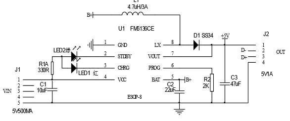
P.S. I just looked at the chip on mine
FM6316CE
Google translate of the data sheet
Schematic
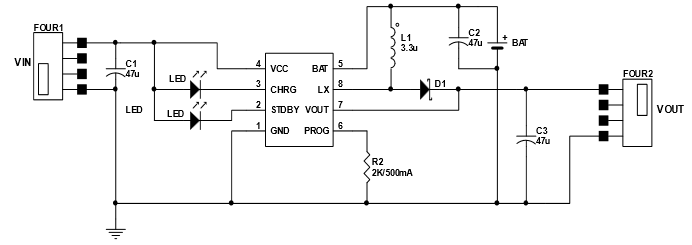
I believe this may be the current configuration on the board
I think I know found these cheapo cylinder and other “cheapy” type chargers cannot charge devices at high enough speed to keep up with the standard drain
180ohm resistor between D+ to D- (the two inner pins)
Many cheap/generic USB chargers have not done this, and the detection of a short (up to 200ohm) between D+ to D- tells the phone “this is a charging device, so you can take full current” rather than the phone trickle charging only from the charger (in my case… and the phone battery runs down faster than it takes from the charger without that short). See the USB wiki, particularly the charging section: http://en.wikipedia.org/wiki/Universal_Serial_Bus#Power
So adding that above resistor on the output of the center pins will let the device know its on a charge device and accept full current rather than trickle charge
Sure enough…just looked, the cheapo cylinder has NOTHING connected to those center pins…hmmm
You do not need a resistor between the data pin, a short is fine.
If you look in my reviews of devices with usb output, I do always specify a coding, this is because there are many ways to signal that you can charge with more than 0.5A. The most commons ones are shorting the pin or using the Apple voltages (Requires 4 resistors).
My 1st one just arrived. It looks pretty good. I’ll pull the trigger on a bunch of these once I confirm it charges the cells correctly & stuff. I like how it looks. It’st least as nice as the ~$20 power bank I bought a few years back(this was before I knew they made user serviceable power banks.) Thanks for the heads up on this item!
*edit - Ending charge voltage on mine was a safe 4.16. I’m using an old battery pack pull so it might be the cell. Anyway these are nice as it charges up my tablet and kindle just fine. I just placed an order for a bunch more. These will make nice casual handout gifts.
I will say this though, don’t expect them to fully charge a device…my kids have kindle fire’s (gen 2 not the HD) and using cheapo red panasoic laptop pulls (maybe 2000mAh) they will put about 20–40 charge on the battery (I believe they have 4400mAh batteries in them) efficiency is fairly high on charge/discharge so they are adequate for single cell mobile power…if these were in 4x or larger box they would alot more versatile but charging them would take FOREVER!
Actually I am thinking of getting a LARGE single cell Lipo battery and making a custom build of one of these
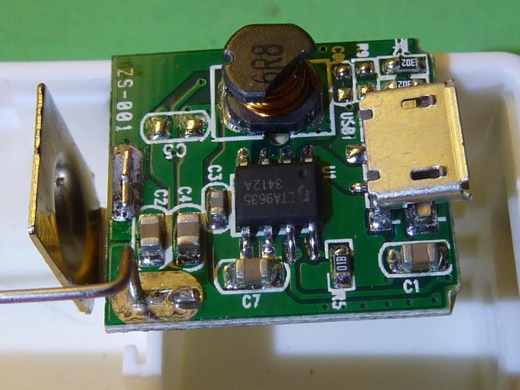
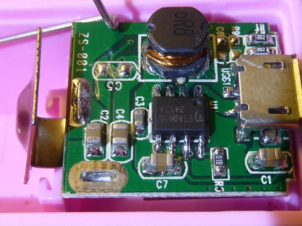
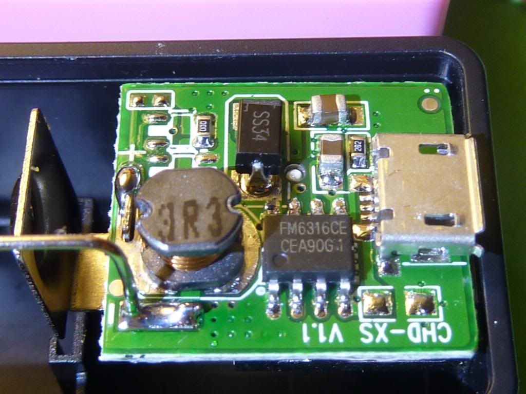
Today I got twoo of these usb chargers/power banks from buyincoins… Its interesting that the white one has ETA9635 and the black one FM6316CE chip. Which one is better? The difference is that on the white one you cannot see the blue led during discharge and on the black one you can - very clearly (I even painted the cover black and you can still see the bright blue led). I will test charging my 9.7” tablet, which is rated for charging at 2A… Great little gadget, especially for the money…
@HKJ: Do you have any plans for testing this thing? I would love to see how it does on your detailed test… ![]()
I do have one and hope to get it tested, but lately there have been many chargers.
Be advised, smoked one already…the one with the FM6316CE chip in it…got INSANELY hot on the USB plug…the other ones don’t get hot…but that one…poof…let the smoke out
But this is what you get for $2.99 cheap Chinese chips…wish I could find some loose…I would unsolder that one and put another one on
I did put a blob of silicon RTV over the chip on 2 others…just to see if it helps move the heat way from the chip…but after doing some investigating…thermally conductive potting is better (maybe 2 part epoxy??)
It’s supposed to have thermal protection, but I think this particular chip wasn’t up to snuff
… wonder if that’s across the board, I’ve 2 black ones on the way. Would expect these chips to behave a bit differently.
WarHawk - Thanks for the heads-up. Wonder if a piece of heat-sink two-part thermal epoxied would fit or help.
But based on this & the other things you’ve said maybe that ($15 fleabay) “ENB USB Power Bank 2x18650”/battery box that HKJ did review is worth considering. E.g. what is our time worth on these things ![]()
I ordered 1 each of White, Pink and Black.
I had to “repair” all 3.
The White one did not have the micro USB connector soldered sufficiently, I re-soldered it
The Pink one didn’t have the spring assembly soldered to the circuit board. I soldered it.
The Black one did not have the spring installed in it’s slot, I had to do that. An easy fix.
Pics of all 3 with the board removed and upside down.
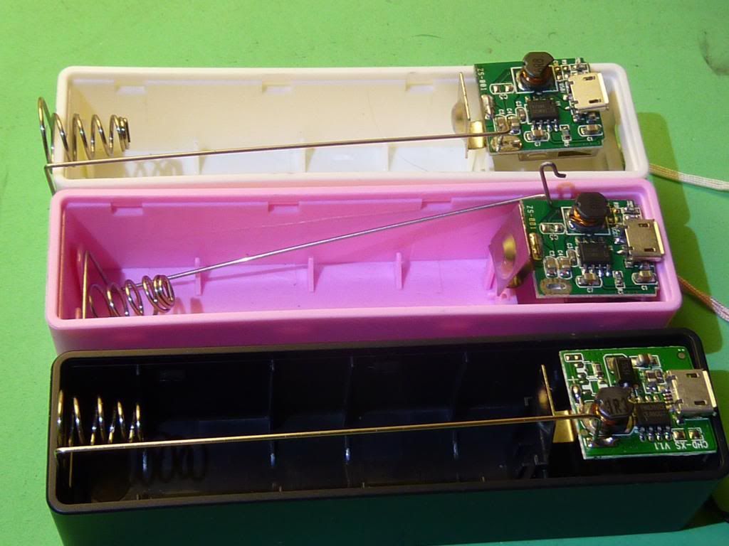
The Black one has a different circuit board and chip as mentioned by others. White and Pink have the 9635, while the Black is the 6316.
I had one that had a cold solder joint on the + spring post (the light would kinda flicker on charge…hmmm)…a quick hit with a 50watt solder tip and viola
I put some clear silicon RTV over the chips as a heatsink conformal coating/potting to see if it helps [just a glob on the chip and let it self level and harden]…these chips get quite hot when they are charging out (I believe they are current limited IN to 500mA so not as stressful on the chip or the battery) they should have thermal protection in them though (per the data sheet)
There is maybe 1/16” space under the board to the bottom of the housing when the board is inserted so maybe putting a small heatsink would help but there isn’t much room and no airflow so there is really no benefit from a heatsink, I was thinking perhaps the potting would wick the heat away and into the surrounding board thus giving the thermal path a larger surface area to dissipate (but I’m no electrical engineer, I just know thru my military experience dealing with silicon/RTV encasulant and conformal coated boards, the heat would migrate away thru the conformal coating)
Maybe I am just overthinking a cheapo charger
First Hi, I especially signed up here to talk about these ![]()
For me it is the same with two different chips, my half black/half white one uses a FM6316CE and the White one an ETA9635. The FM chip uses less external parts, 9 C’s and R’s or LEDs, not counting the big diode (SS24 for me). The ETA uses 11 C’s or R’s or LEDs. The FM board says CHD-XS V1.1 and the ETA board says ZS-001.
In my case at the start both worked fine, with the FM6316 also lighting Blue while being discharged and being at about 4V idle (Multimeter measured), it only went to 5V on discharge, so it somehow detects discharge? I first though this is nice!
However, this didn’t last very long, after trying to charge Tablet and Phone a few times (just for some seconds or minutes) it didnt charge any of them anymore and the blue light also didn’t light up. Now it is permanently at about 4,1V output - however this is NOT the direct battery voltage, which I thought first - it is always slightly boosted. Interestingly it drops slightly (idle) (to 3,9V) when it is getting charged. The USB-Out Plug is also minimally heated while the battery is connected (didn’t check if it also was before), so probably it’s draining power unneccesarily - charging works however!
I checked the board and didn’t find any bad joints. I also resoldered some to be sure… So I guess the FM chip is fried - But at least I might be able to use it as charger-only. Good that I ordered two of these Powerbanks, but really strange that they don’t only differ in Color.
My guess is the FM-variant is the cheaper-made and newer variant, because it also has fewer external parts. But overall, both of these small PCBs had some parts not populated, either this is just for a different setup, or there were some protection and stability elements of the circuit removed. If I would know, I would be happy to add them, but the datasheets to these ICs are quite bad …. (Thanks for the google translate link to the FM datasheet by the way!)
Btw. I actually ordered them to try if they would work as a Raspberry Pi uninterruptible power source (UPS). I tried the ETA based one (as the other was dead before I could do that, like I wrote before…). The output voltage dropped too much, to 4,4V at the two relevant measurement points on the raspberry pcb (while it is spec’ed for 4,75V - 5,25V, 700mA, though they recommend a 1300mA+ power supply). So they really don’t seem to put out a stable voltage at higher currents ![]() or maybe I should try to find if this can be changed by a resistor.
or maybe I should try to find if this can be changed by a resistor.
(Got the ETA9635 “datasheet” from there: http://www.datasheet4u.com/datasheet/E/T/A/ETA9635-ETC.pdf.html - anyone knows a better one?)
I had 3 that all seemed to be working OK but you guys got me curious. I pulled the guts out of the plastic housing and broke off the mini-USB port. I did try to be careful. My skills aren’t up to re-attaching that little thing. Pretty fragile little part. I pulled off the copper pad on one of the 4 feet anyway so doubt I could have ever gotten a decent connection.
The law do diminishing returns. It goes both ways.
As you try to increase the performance of an item, the cost goes up with less and less improvement.
On the other end, as you try to lower the costs of an item, you reach a point were each cost savings that you implement impacts the performance more and more until a point is reached were functionality is lost.