I can only speak for myself but it's basically because they are bloody difficult to get right and take a lot of time to get working. For the most part, linear and DD drivers take all of 5 minutes to get a basic design working. I'm more than happy to open source the basic stuff but the drivers that take hundreds of hours to get right are a different story.
On the other hand I'd be more than happy to contribute to a team designed open source switch mode driver.
It’s not so much an emphasis as hopefully a starting point. A bunch of boards were designed in a short time and it made sense to me to get them all together. Any flashlight related Oshpark projects would fit the bill and I’d love to have boost and buck boards posted as well. Help us find them!
Yep, available online. I can’t seem to copy /paste a clean link from my phone, but if you Google it, the first result is a datasheet. It’s about the simplest buck IC you could ask for.
I'm working on a series triple AA carrier for djozz at the moment. If I get that done tonight I'll do a parallel carrier as well. Any specifics? BATT+ and BATT- available at the front? Or BATT+ front, BATT- rear? Overall diameter requirement or just as small as possible with 4xAA cells?
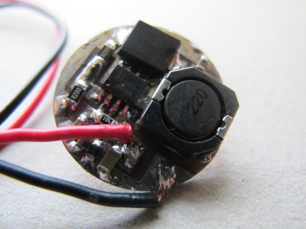
This is one of my AX2003 board in EAGLE. Dropbox - 22MM_2.5A_104R.zip - Simplify your life You may download and have a trial.
Please note that the bottom layer is the ground which work as a thermal pad.
If you want batt+ front, batt- rear, it seems like a waste to pay oshppark for that. Pretty much just a couple sheet metal or copper plates with springs.
What will be used as the supports / pillars. I’ve been thinking about what could be used that should be commonly available anywhere.
An easier rule of thumb (at least the one I follow) is that as soon as your 3x boards from Oshpark hit just above the $10 mark, you’re better moving over to iTead, where that $10 (a bit more because they charge shipping) will get you 10x copies instead.
With parallel? Isolation is easy, no?
Maybe I’m cheap? PCBs certainly looks better & more finished. $9 for 4xAA top plates +$9 for bottoms. Pushed mine down to $7.45 if its squared off a bit.
Sorry if that came across as abrupt but your description of two metal plates was a bit lacking in detail. Sure I could make something and often do but other times it’s nice to have it already done. There are several more options I’d like to see as well and I like your use of solid wire to beef up the vias.
I could really use some generic SMD switch PCBs. Isn't the lead spacing pretty close on all the various common switches, or close enough that the pads could be enlarged to make it compatible with nearly everything? I'm only familiar with what fits into SRKs and their clones, are there other lights that use larger PCBs, such that it might make sense to do a larger universal board with silkscreened cut lines for the various ODs?
With the SRK drivers with piggybacked 105Cs I always add two pins on the back of the switch board, and then put connectors on the ends of the wires because it's too much trouble (or impossible) to unsolder the wires from the driver.
What are these connectors called? They're used for all kinds of things but I have no idea what their proper name is...
It has 3mm holes (actually via's) so that I can solder 3mm brass rods in, but other materials can be used if you use screws (even M3 threaded rod can be used with nuts), the rods are not part of the electrical path (apart from that they are connected to batt - )