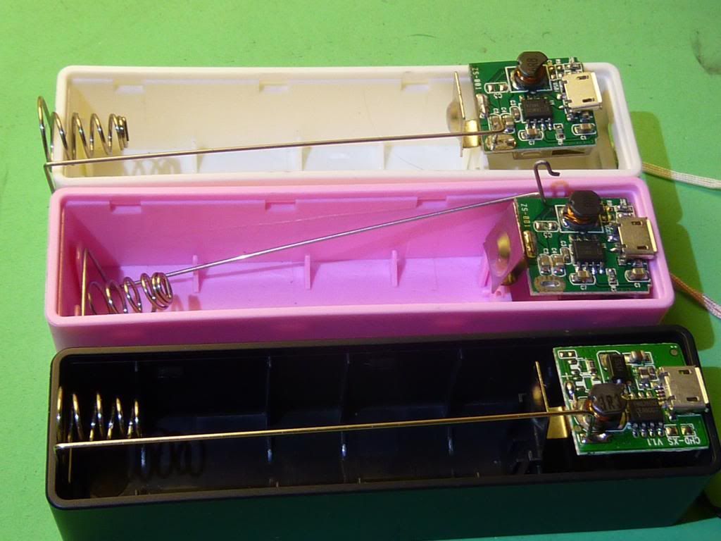
First Hi, I especially signed up here to talk about these 
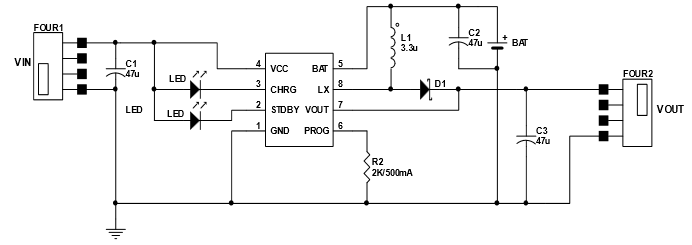
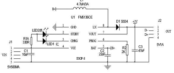
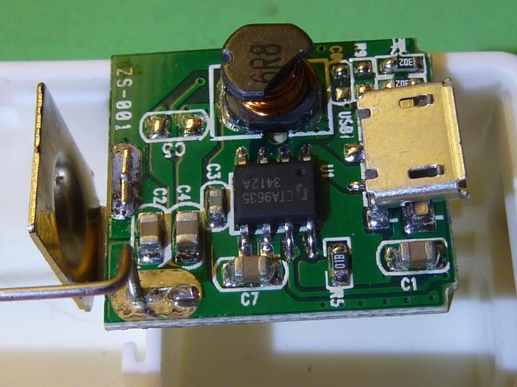
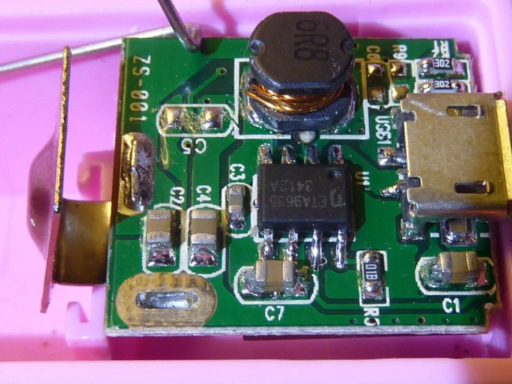
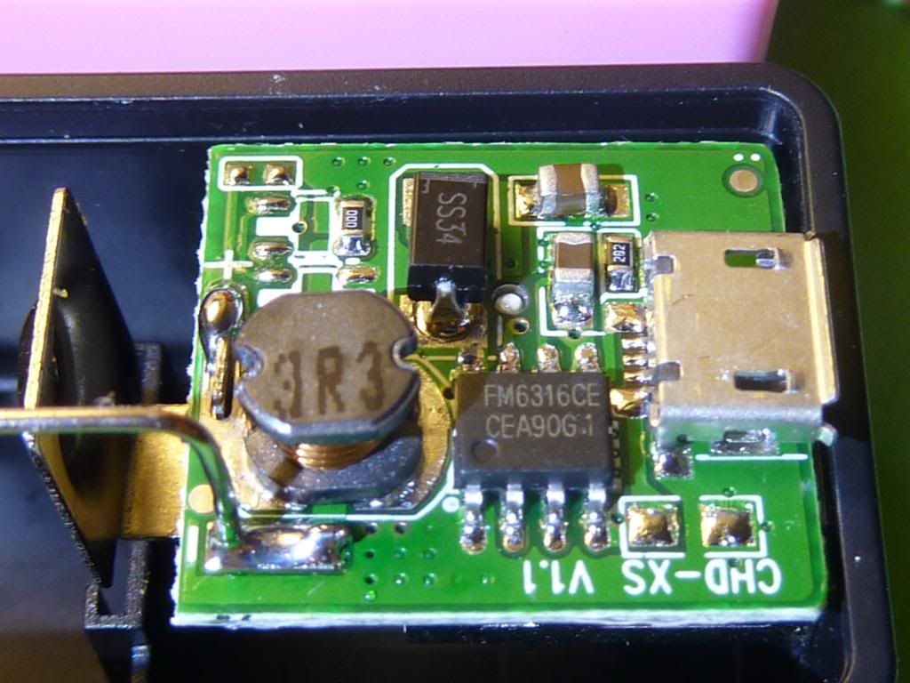
For me it is the same with two different chips, my half black/half white one uses a FM6316CE and the White one an ETA9635. The FM chip uses less external parts, 9 C’s and R’s or LEDs, not counting the big diode (SS24 for me). The ETA uses 11 C’s or R’s or LEDs. The FM board says CHD-XS V1.1 and the ETA board says ZS-001.
In my case at the start both worked fine, with the FM6316 also lighting Blue while being discharged and being at about 4V idle (Multimeter measured), it only went to 5V on discharge, so it somehow detects discharge? I first though this is nice!
However, this didn’t last very long, after trying to charge Tablet and Phone a few times (just for some seconds or minutes) it didnt charge any of them anymore and the blue light also didn’t light up. Now it is permanently at about 4,1V output - however this is NOT the direct battery voltage, which I thought first - it is always slightly boosted. Interestingly it drops slightly (idle) (to 3,9V) when it is getting charged. The USB-Out Plug is also minimally heated while the battery is connected (didn’t check if it also was before), so probably it’s draining power unneccesarily - charging works however!
I checked the board and didn’t find any bad joints. I also resoldered some to be sure… So I guess the FM chip is fried - But at least I might be able to use it as charger-only. Good that I ordered two of these Powerbanks, but really strange that they don’t only differ in Color.
My guess is the FM-variant is the cheaper-made and newer variant, because it also has fewer external parts. But overall, both of these small PCBs had some parts not populated, either this is just for a different setup, or there were some protection and stability elements of the circuit removed. If I would know, I would be happy to add them, but the datasheets to these ICs are quite bad …. (Thanks for the google translate link to the FM datasheet by the way!)
Btw. I actually ordered them to try if they would work as a Raspberry Pi uninterruptible power source (UPS). I tried the ETA based one (as the other was dead before I could do that, like I wrote before…). The output voltage dropped too much, to 4,4V at the two relevant measurement points on the raspberry pcb (while it is spec’ed for 4,75V - 5,25V, 700mA, though they recommend a 1300mA+ power supply). So they really don’t seem to put out a stable voltage at higher currents  or maybe I should try to find if this can be changed by a resistor.
(Got the ETA9635 “datasheet” from there: http://www.datasheet4u.com/datasheet/E/T/A/ETA9635-ETC.pdf.html - anyone knows a better one?)