The only little thing I can find is that the pin2/pin3 selector thing for the switch input could be tricky when removing/replacing the switch wires, if it's done at the driver (if you use a wire lead to bridge the gap, the soldering iron will tend to suck it up when removing the switch wire). But I tend to tear things apart and tinker much more than most 'normal' people, and I plan to still add a 2 pin header on the little switch PCB for that reason anyway, I don't like unsoldering stuff when I don't have to. That's a very minor thing and I'm weird, it will probably never be an issue.
Warhawk, I dunno, but Richard is going to be selling them, gotta mod one. Gotta! That driver is just compelling. I feel drawn to it like a moth to a flame. (And if you have seen me solder than you’d know that analogy fits perfect). I figured one of you knew. I will do a search on some of the reviews.
Matt, an idiot? Not from what I have seen. A poorly phrased question I will grant.
Good call. I thought about it but haven’t done it yet. Some of the work was done behind the scenes but there are certainly parent threads even for those.
I believe the M6 has a larger ID driver compartment than the SRKs, so if it fits the SRK it will fit M6 with plenty of room to spare. Drivers that fit the M6 will not necessarily fit the SRK (I think DrJones ran into that issue on the one he did recently).
In a SRK...

That capacitor kabob thingy smooth out the current so no whining?
It does on the original mule PCB (the red 'JB' driver), this is the same circuit just on a new board so no reason it won't do the same here.
So very cool.
Comfy, these are the parts that I need here. I think you linked them somewhere before. The tiny13 will need to be flashed right?
Yes, MCU will need to be flashed. Add one of these to your Digikey order, it's cheaper there than ebay: http://www.digikey.com/product-detail/en/5250/501-1311-ND/745102
And then these for the rest of the stuff needed:
http://www.fasttech.com/product/1002900
http://www.fasttech.com/product/1011800
http://www.fasttech.com/product/1135300
comfy, that's the cleanest board I think I've ever seen! All purty for the pics!
I ordered the 7135 based 46 mm's because I got a ton of 7135's now and need to use them on something, and think'n I'd like to keep the SRK lights regulated, somewhat anyway - I'll still pile on 7135's, but more in the realm of 3.5A per LED. Also ordered the 17mm and 20mm FET based boards.
Comfy, that’s awesome. However, thinking of my recent experiences,

And also

Maybe I should just harvest a tiny13 that’s been flashed and reflow. My soldering is getting better since I trashed the MTG2 driver- but it’s not good. Although, my ego and enthusiasm make up for it ![]()
Well I am still getting some squeal, but this is the first one built. Time to start swapping parts and see what changes it. It was silent on the JB board but I was using a different inductor. I need to try it with no inductor, and with the other inductors I used before. I do know for sure it would be louder without the big capacitor, that's never failed to show a big improvement. This PCB is thinner than the other SRK boards which can also have an effect on PWM noise (different resonant frequency).
Another weirdness I didn't see before: after disconnecting power then reconnecting (like swapping batteries), it turns on in the lowest mode even without any input from the switch. A long press drops it down a mode and it turns fully off like normal. This is the exact same code I used on the test boards so I have no idea what's different now.
I also need to flash it temporarily with a FW that has a battery monitor mode to see if this diode (D1, the little one) has the same voltage drop as what comes on the 105C.
The capacitor isn't holding a charge by any chance and plus providing a false "on" signal to the MCU?*
- Matt
* I've put not thought into this comment what-so-ever.
That was Mattaus’s handywork on the build of the OSHPark board (and design thru Eagle), comfy and rufus giving expertise…and me just being able to cheerlead them on
That is what I did with TexasPyro 20mm Nanjg…ended up flashing it to STAR V1.1 though, it caught me off guard because I thought I already flashed it…but started getting the flashies…hah
Maybe I will just offer my services for soldering and flashing drivers (for a small nominal fee)
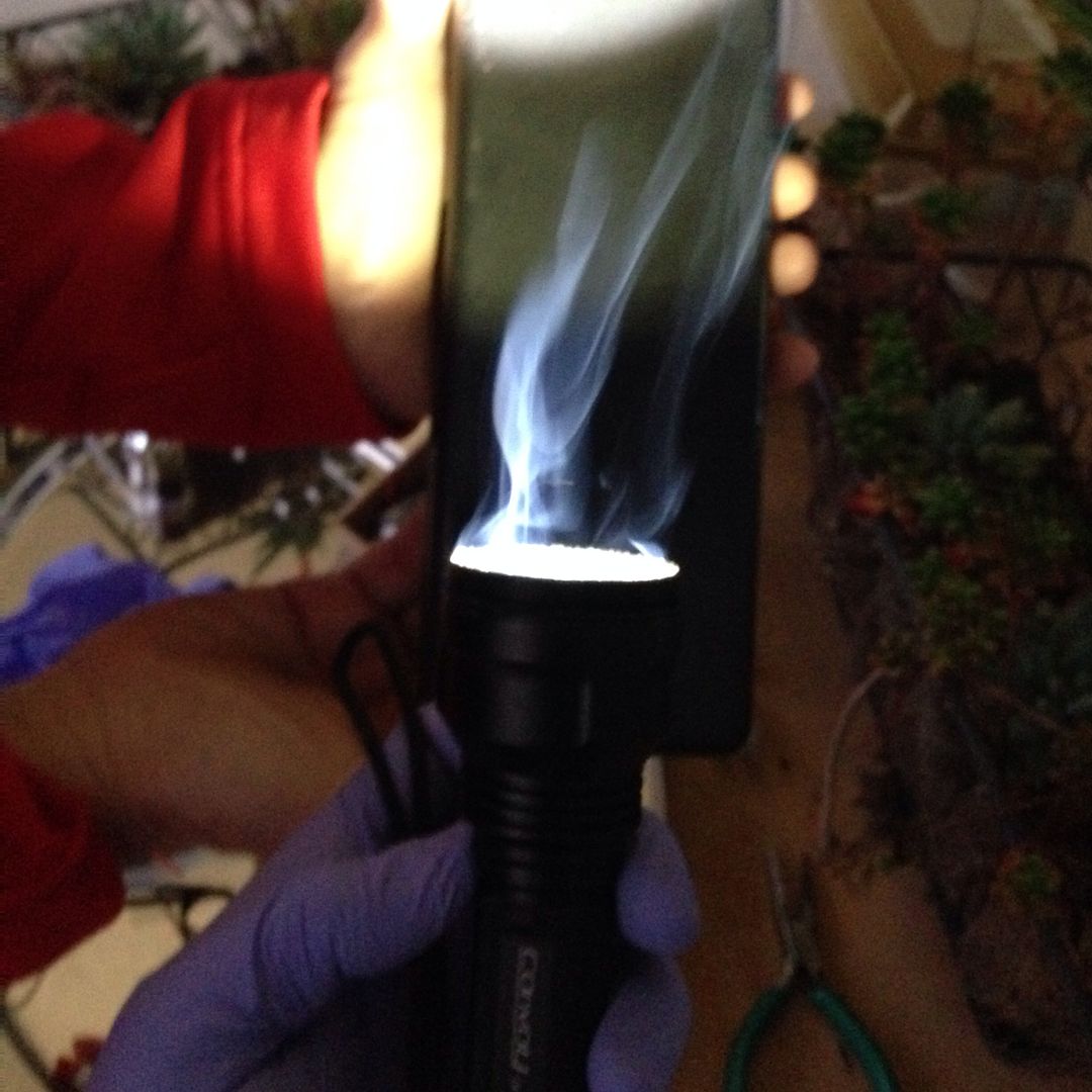
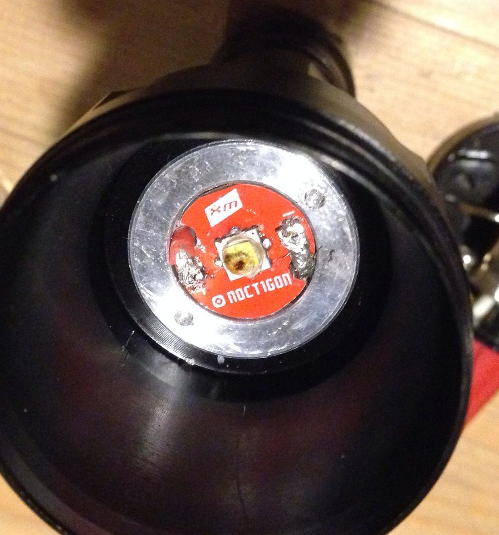
and OUCH on the smoking of the emitter…dang, but it happens
It’s embarrassing, but a learning curve with lots of help and support from the tutors here at BLF. I’m getting better. My patience or lack of patience is my downfall.
Nope, if I disconnect power while it's on I can see it drain the cap, as it fades down to nothing which looks different than blinking off instantly when turned off via the momentary switch. I did try shorting the cap to drain it before connecting power but it still does it just the same.
Maybe I missed it, but for the 15 mm DD FET driver, has anyone tested that FET, or assembled/tried this driver yet? Do we have a good feeling this FET and driver will work ok?
Anyone have a DigiKey listing for the FET?
The fets were used by Werner but I would not call them thoroughly tested. By itself one blew but I think that was with an 18650 so he designed his board for four but that is still testing. That size driver is meant for 14500 applications where the current available is less. It should be ok with a 10440 but might need 2 stacked with an IMR 14500. This is hypothetical at this point as I have a few but haven’t tested them yet. I can pop two in the mail if you want to try them out. I got them on eBay for less than .30 ea. I was going to try one out on a blank single mode board first but that won’t happen til the week end.