CREE XB-H 16mm with copper on top
Shouldn’t really provide much benefit if the bottom is attached to a heatsink / pill.
Should it have the little over flow channels on the actual led pads? Makes the pads look like “T’s”.
![]()
You can do 1.5A regulated inside 10mm, non-stacked. You just keep telling them to squeeze in a wee bit more. Promise them sweet copper for dessert if they keep the complaints to a minimum.

Yea, I noticed it was missing. You’ll see the actual oshpark link goes to a slightly different version then that picture was from.
The pulldown resistor is there to drain away any floating charge on the gate pin when the MCU is switching the PWM output on/off/on/off to get the less-than-100% modes. I thought someone had mentioned a while back that the tiny13 has internal puldown resistors to handle that and an external resistor isn't needed, but adding one definitely does have an effect, at least on the boards that have issues with mode switching.
I still don't understand why the 105C components+FET work fine without the resistors when on the Nanjg PCB, but don't work without them on the 17DD PCB. (that's when using the phase correct PWM only, adding resistors to the Nanjg might enable use of fast PWM on that one like it does on the 17DD)
Oh, I didn't post this earlier but I did test an original 105C diode in place of the Digikey ones, and it had no effect. So none of this is caused by incorrect diodes.
Ok, I’ll post it in the op after the triple XML.
Hey Dale, if you can, try it on one of the Oshpark Tiny10’s. If you cut the 7135 ground pad between the tab and the center pin you can solder the gate pin to the now isolated pad and use a 100 ohm resistor to jumper that back to the original pad.
Edit. Until it’s repeated, it didn’t happen or can’t be said to be reliable so let’s see if we can’t make it so.
Comfychair, can you update the shopping cart with the two extra R’s and I’ll swap them into the op?
Which value on the gate resistor? I tested a range of them and it's still not completely reliable even at 78 ohms, which makes me think 100 ohms may be cutting it a little close, I used a 130 on mine. Going too high matters too, more resistance there makes it less sensitive at the very bottom of the PWM values ('1' no longer works with even a 100-ohm at the gate, has to be '2' or above to light up).
I can try that Scott, will do today, but it won’t work in my TP. Pretty much have to have a contact only on the battery side of the board. The body is machined with near zero tolerance, if the contact to the battery get’s any longer from the board mount position, that will keep the battery tube from screwing in all the way and possibly cause a breach around the water resistance the o-ring provides.
I’ll build the Tiny 10 this way and check it out. Then if I can duplicate it, I’ll see if I can rebuild the PICcolo board for the TP. (fingers crossed, which is gonna make it difficult to do this board. ![]() )
)
I defer to your experience here but it seems the lowest reliable value is in order. 100-130 is a place to start and it can be changed if needed. 10K on the other, correct?
Yes, 10k on the pulldown. That's low enough to provide a drain, but too high to affect the signal delivered from the MCU.
Instead of having to buy separate 10K resistors, you can use the 4.7K value used in the battery monitor circuit.
The picture I’m getting is to put that 100 ohm resister under the FET, jumping between the outer ground pad and the smaller inner ground pad. ?
Would the 19.1 work too or is that likely too high to be effective? I haven’t tested anything over the 10k I used, other than to see that it makes a difference when it’s not there.
Any ideas about what's different between the big PCB & little PCB that would require one to have the resistors and the other not?
Close, between the control pad and the center pad for the 100, then leave 2mm of ground trace for the FET and cut the ground trace. The 10k goes between the FET control and ground pins so it could go under the FET but doesn’t need to. The drain will need a jumper. As small as the FET is, there’s real estate for all 3 parts without stacking. Well just need to ask Matt to set it up. Hey Matt! :bigsmile: 
Surely that tiny little FET takes less to drive than the big ones, does it need the gate & pulldown resistors?
No middle modes without the 100ohm on any cell. I don’t have the pull down 10k so can’t tell you. With 2 fets it seems fluky with higher drain cells(low modes jump up) and with 1 behavior is erratic(sometimes fine then a minute later not). Somewhere north of 1.5A is where the erratic behavior begins as it was consistently well mannered below that point. It seems to handle more than 2A well enough so maybe the 10k will fix the middle modes at the higher current? I would give much credence to the numbers posted in an absolute sense as there were a number of extra clips, cheesy meter wires, and solder connections involved. Reducing wire lengths and connections could easily change lots of values and operational details. This was just a run through to see what to try next using ready to hand parts. I’ll also need to play with the different stars as #4 was all off. I think a different chip might be in order for the blf15 as some of the cells I used are easily capable of topping 3A and none did more than 2.1A but I should try it again with better shorter wires before that choice is made. Some good testing done but plenty more to do.
It’s quite a bit brighter without the meter in the circuit so when Dale gets his hooked up maybe he can get some decent numbers. Anyone know what’s different about the firmware for star 4?
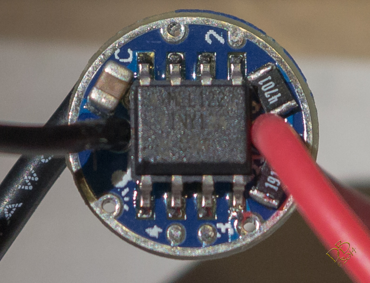
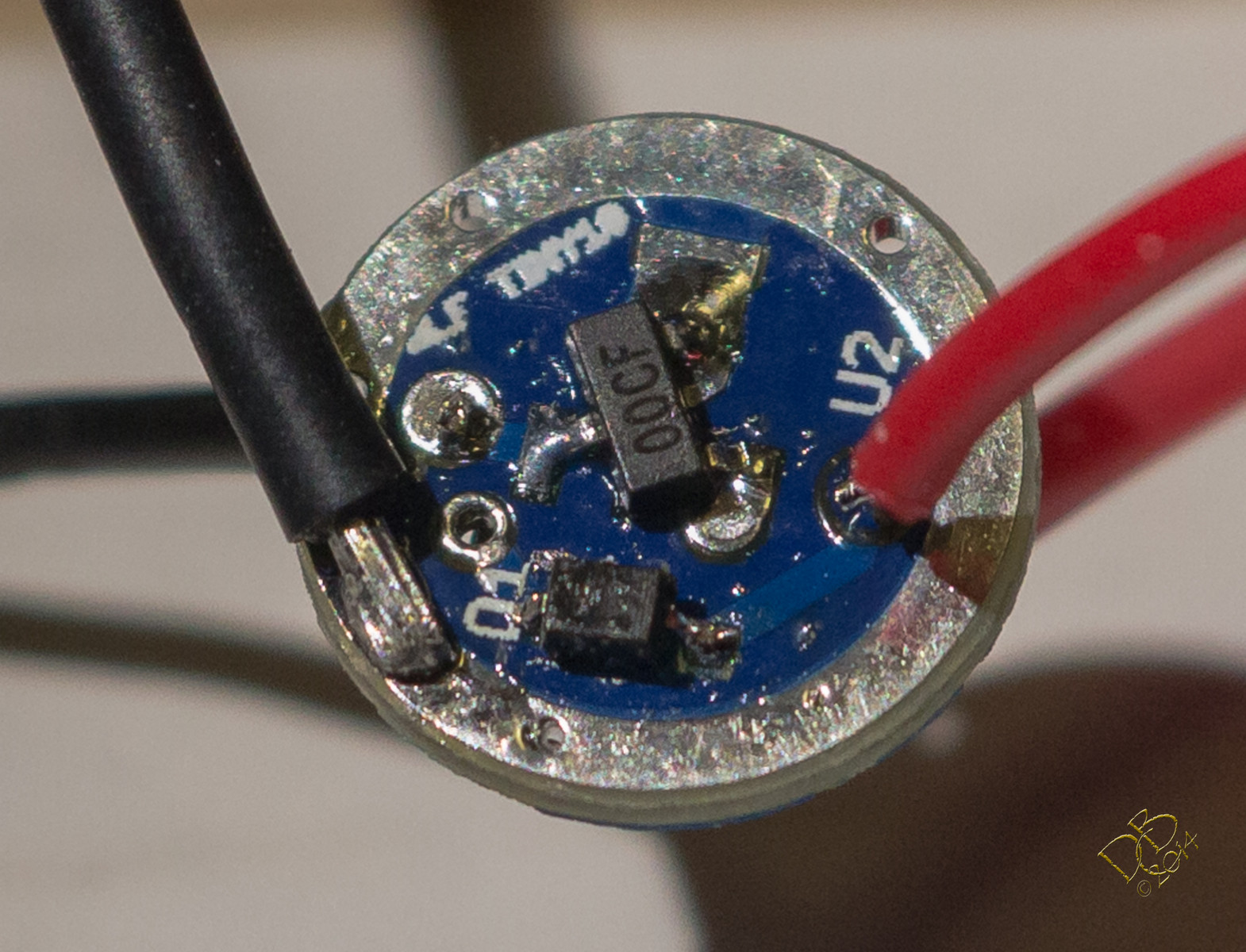
I used a new ATiny13A, flashed it with my FET hex file, all new components except for the diode, which I took off a Qlite board since it’s so small and the new ones I have are TRex’s by comparison.
I used a solder mask to re-flow the MCU side of the board, it’s gorgeous, very neat and everything appears to be sitting just exactly where it fits best. Those 2 resistors are VERY close to the MCU pins but there just ain’t no room on this thin BLF Tiny board.
I did some of the best soldering I’ve ever done on the backside, did not put a resistor in the circuit as it’s such a small FET and the current will be so low I didn’t think it’d need it. Beautiful piece of work, I’m so proud! ![]()
But it doesn’t work.