15th June
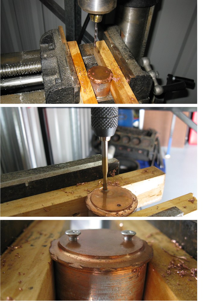
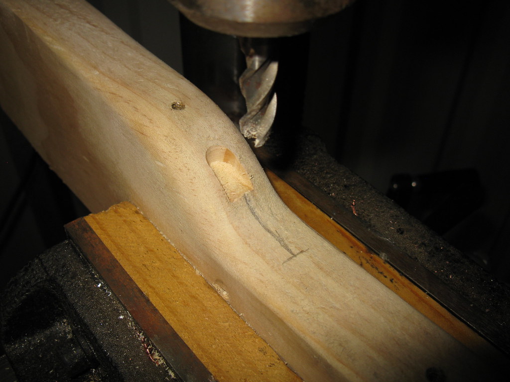
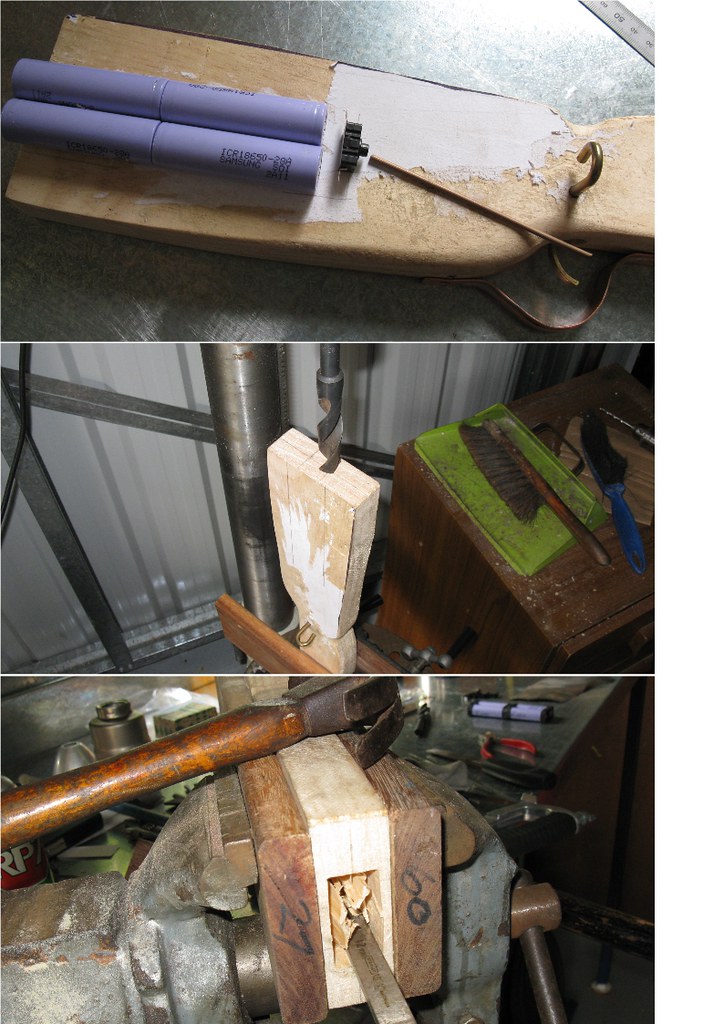
I started off today by boring the holes to take the wiring through to the front of the stock.
All of the wiring through to the front is 18awg, taken from an old PC PSU.
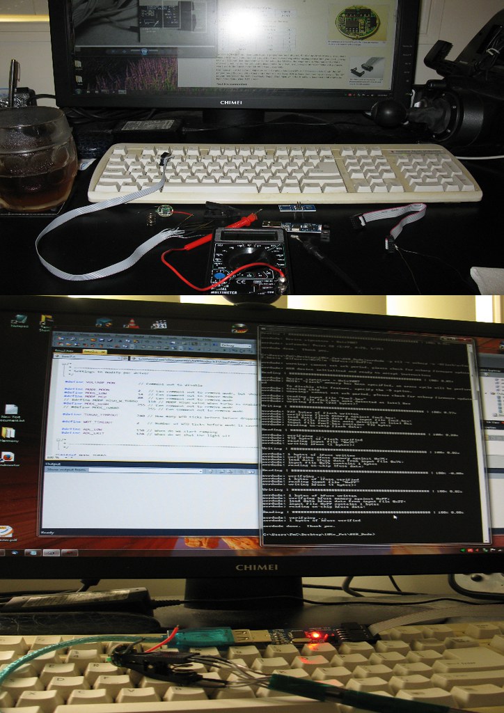
Once done, I wanted to test the circuit, & also the trigger operation for fine-tuning.

....I don't know if anyone picked up on my wiring boo-boo from the pictures yesterday....
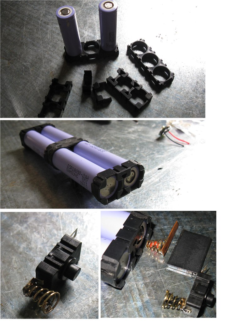
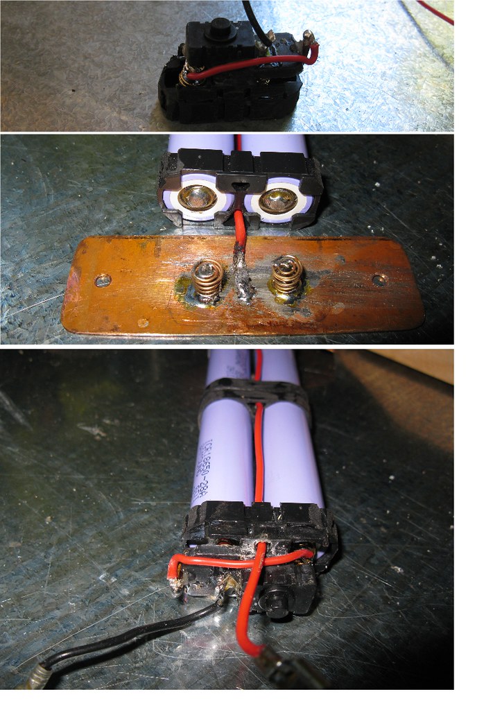
Test voltage was 14.8v ....I had configured the power pack for 4s instead of 2s2p.
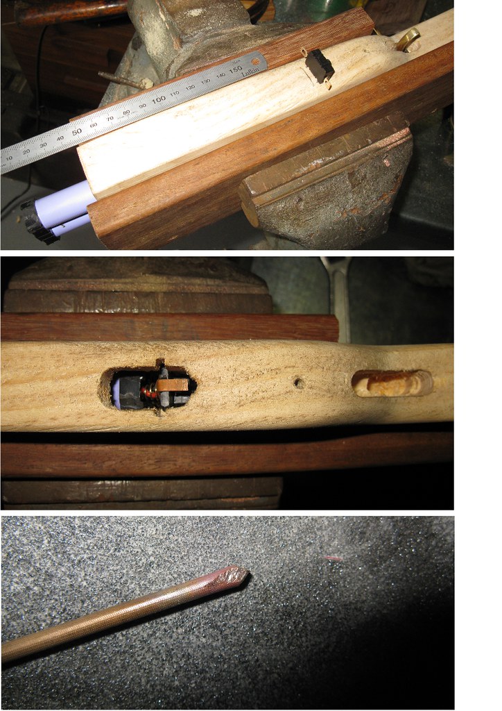
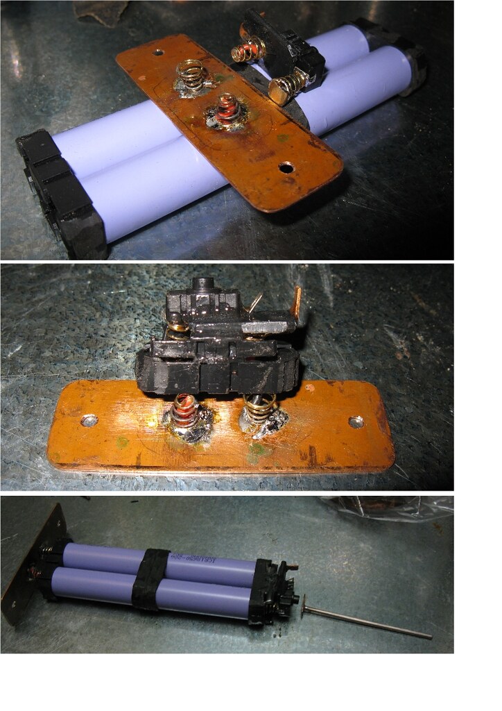
I was committed with the switch design & dimensions, so I had to re-wire the power pack.
The switch was easily re-configured by looping a wire around to join both the negative springs.
The copper end plate now becomes the positive end, with a wire running up through the center of the pack, which will go straight through to the driver & fan at the business end.
I had to use some automotive spade joiners to separate the wiring, to facilitate easy removal of the power pack in order to charge the cells;
Now that the voltage is good, I wanted to do a quick load test & Amp check.
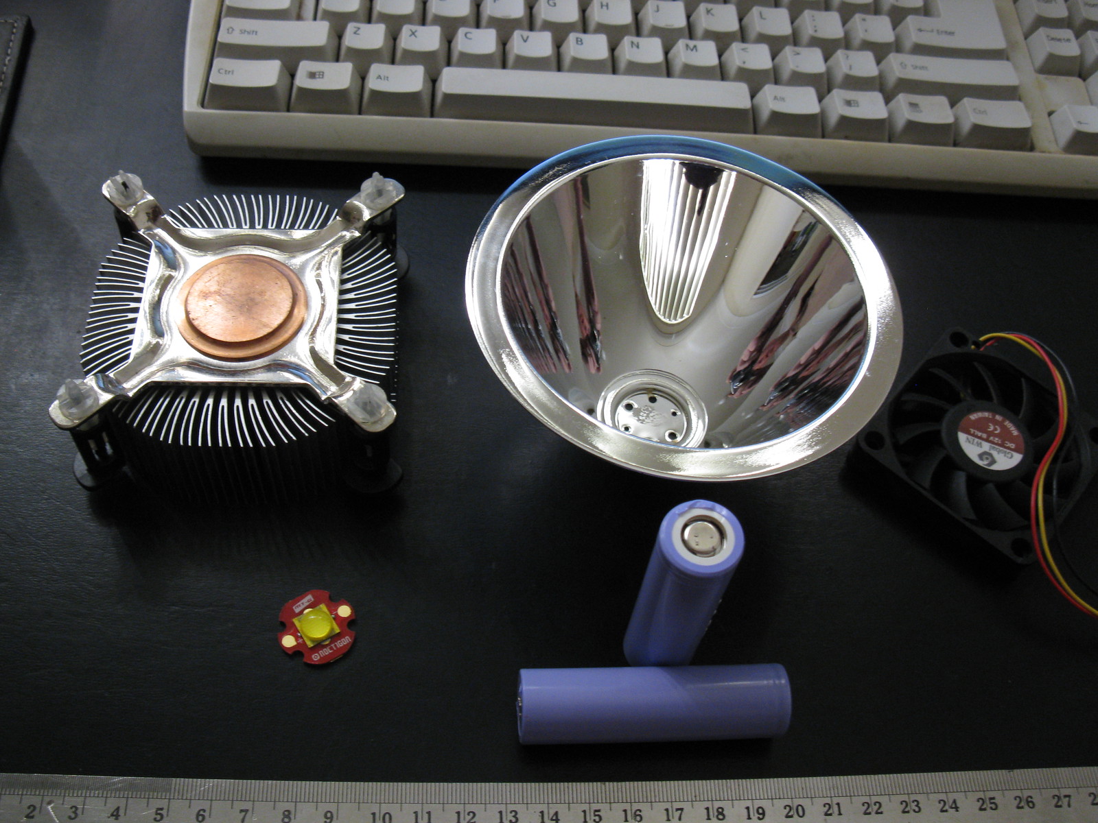
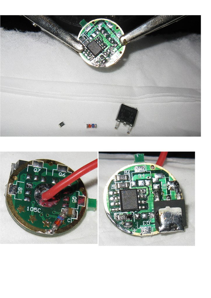
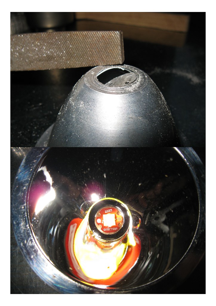
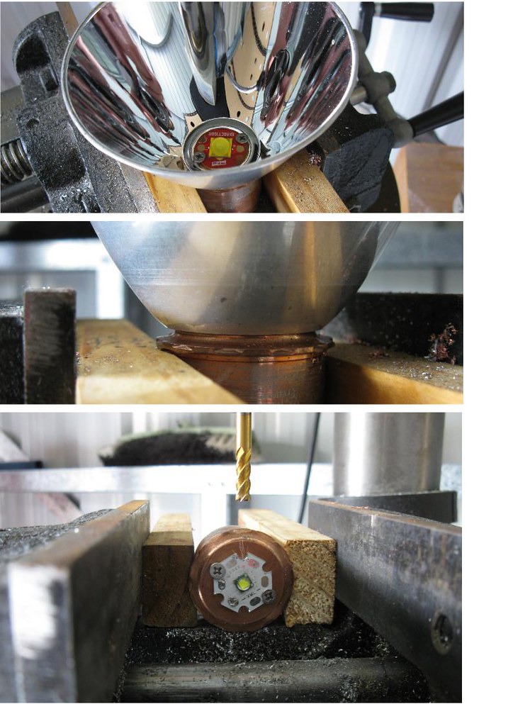
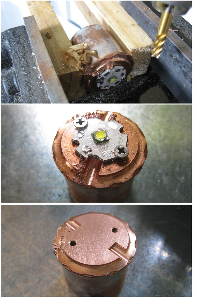
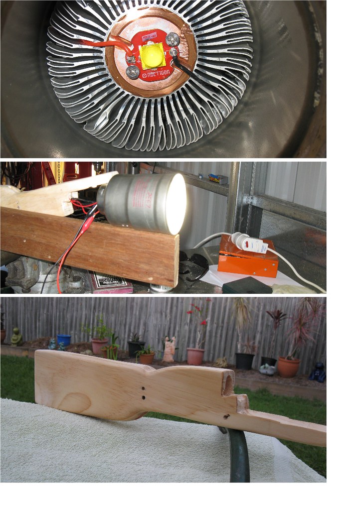
I quickly re-flowed the MT-G2, as I could clearly see a gap between the LED & board.
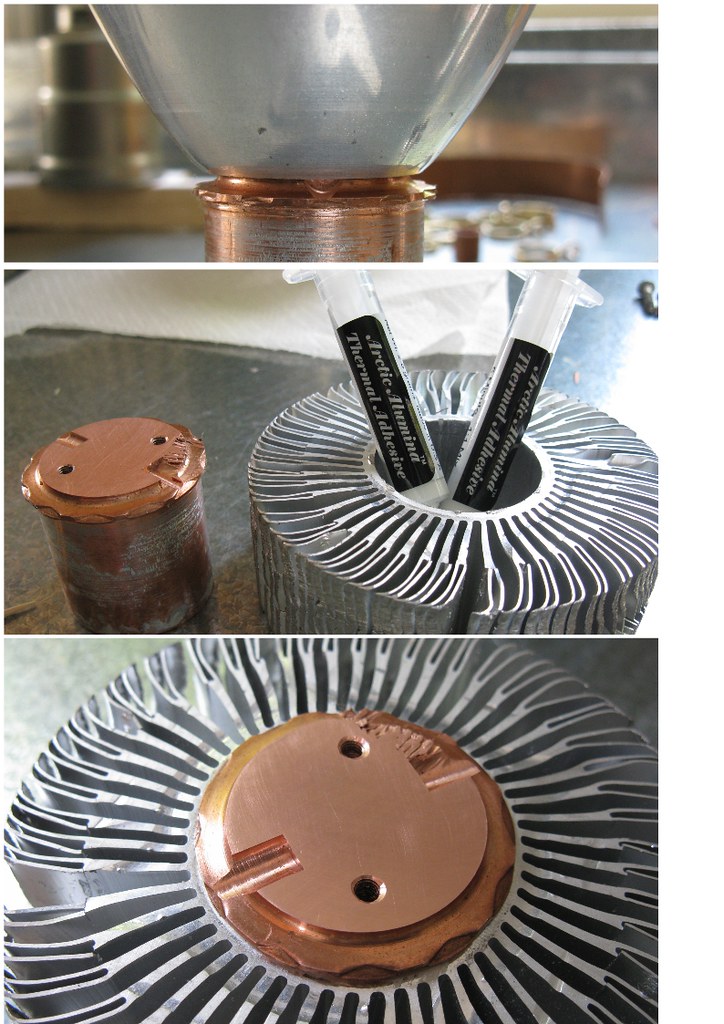
After lapping, I used whisper of Arctic Ceramique, & attached it to the heat sink.
A test fire in mule-mode showed everything was working well. With the long jumper cables to the meter, & batteries fairly low, it was showing just under 4.5 Amps.
With the test fire complete, everything was stripped from the body, & a cavity for the driver was bored into the front of the stock.
With no more major work needed to be performed on the stock, I set about finishing off the contour, & started sanding in preparation for varnishing.
Saturday 21st update
The first coat of varnish was applied to the stock this morning - it will take until tomorrow to dry enough for a light sand & re-coat.
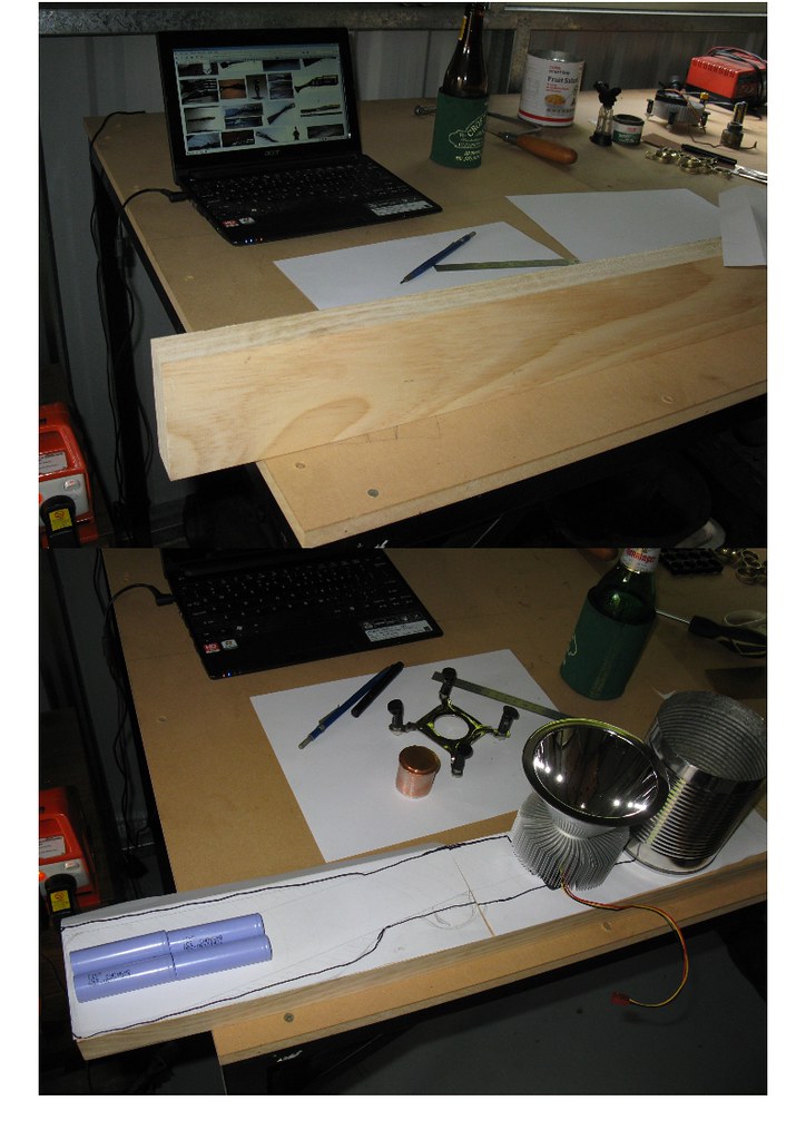
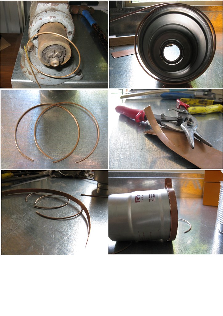
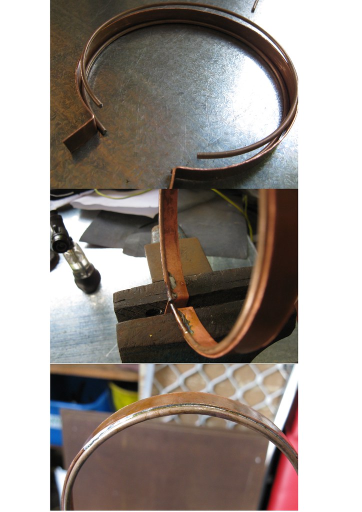
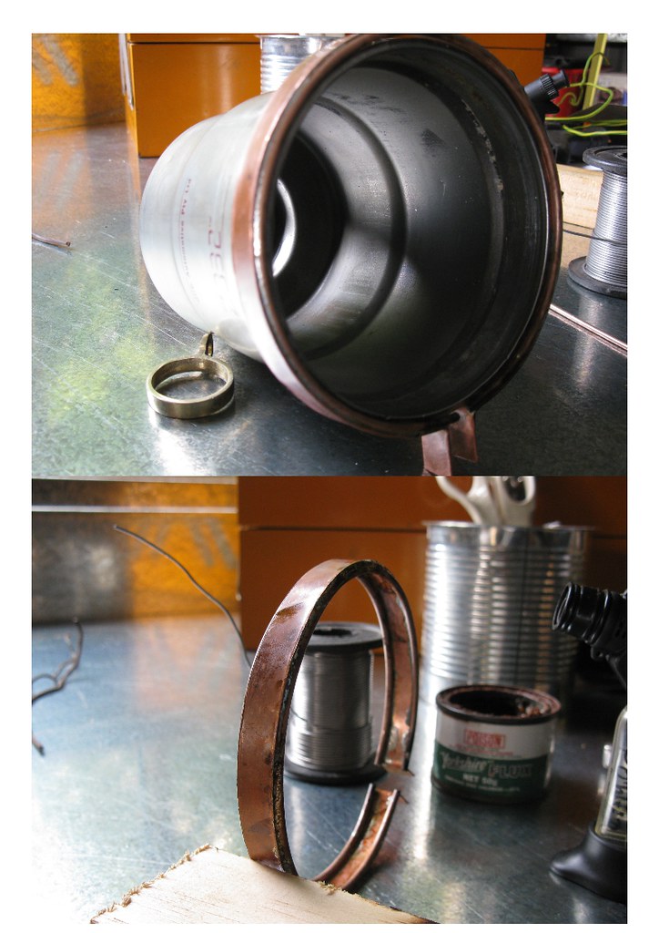
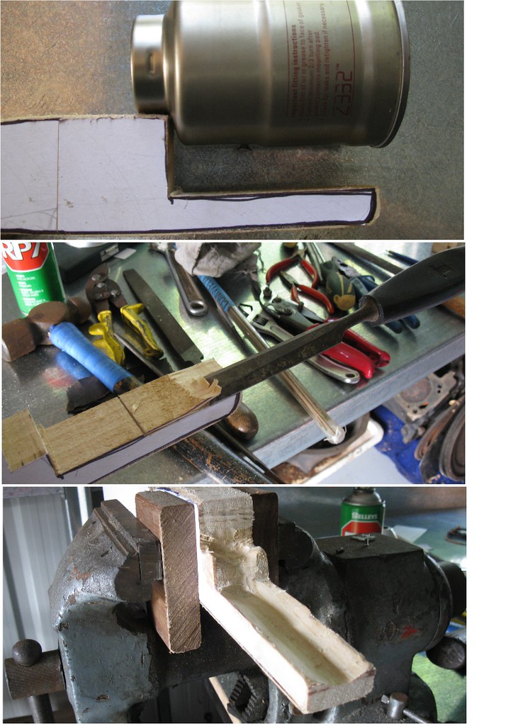
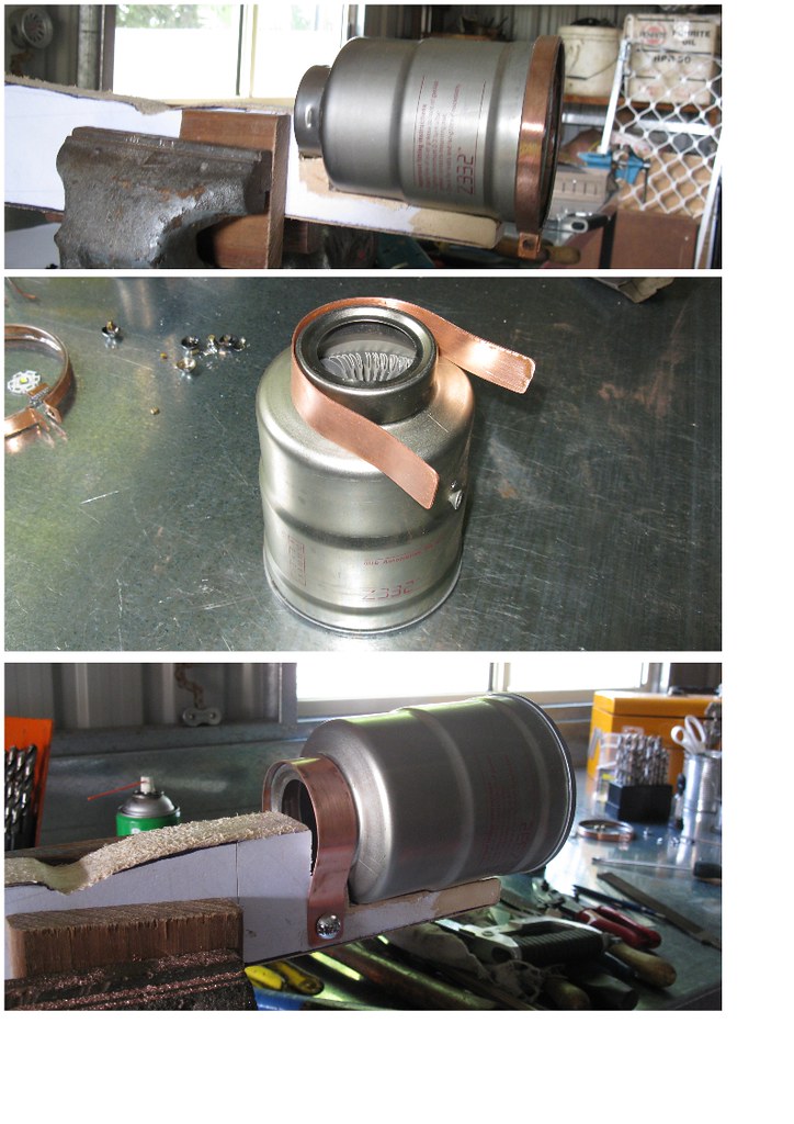
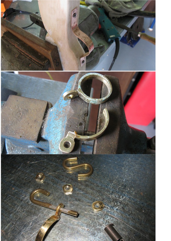
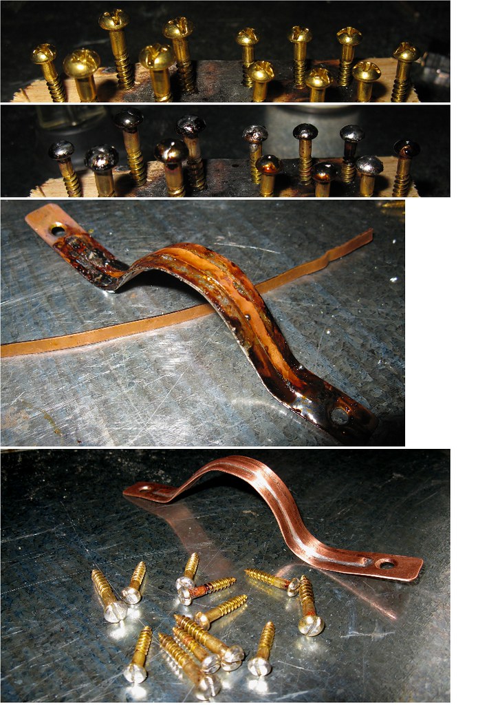
The rest of today was spent making a few more components, & cleaning up all of the copper & brass, ready for assembly.
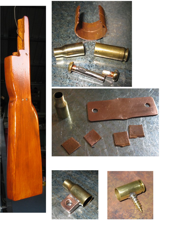
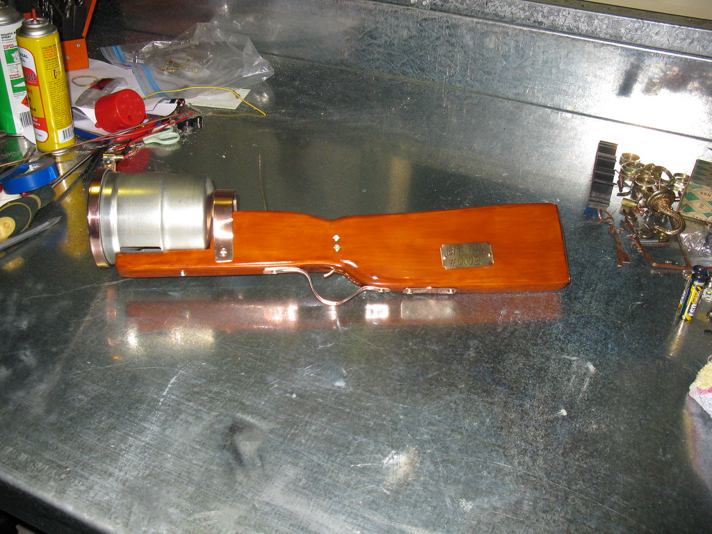
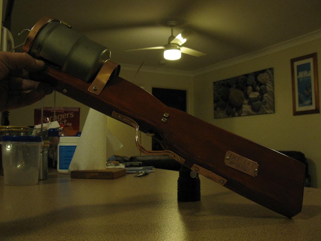
Here's the stock as it looks now. The other parts are a plate made from a round plumbing joiner that will cover the wiring connections for the battery pack, & the front sight that was made from a few copper off cuts, filed square, & soldered to the front half of a .223 shell.
I'm thinking of using the rear half of the shell for the rear sight, but it will have to be mounted higher on the stock, so the brass screw that is currently soldered to it will have to go in lieu of something else. ....or I might just use something else altogether... We'll see what happens tomorrow!
Sunday 22nd update.
I sanded back the stock earlier today, & applied another coat of varnish. It was still a little too tacky to sand...damn cold weather... No point posting another pic of it now - looks the same as it did in the previous pic above.
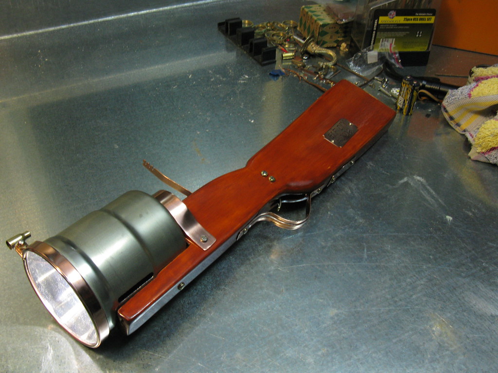
I decided not to use the end of the .223 for the rear sight. The only action it's getting now is in this photo, to prop up the new sight that I made from a strip of copper. It will be bent & attached when the rest of the parts are on, in order to get the height correct.
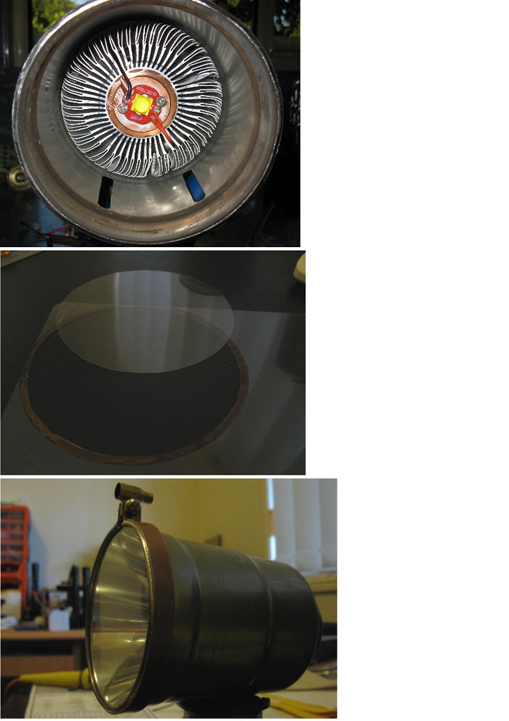
The barrel still needed a little work; I cut the breather vents into the underside, & removed the red print with some thinners.
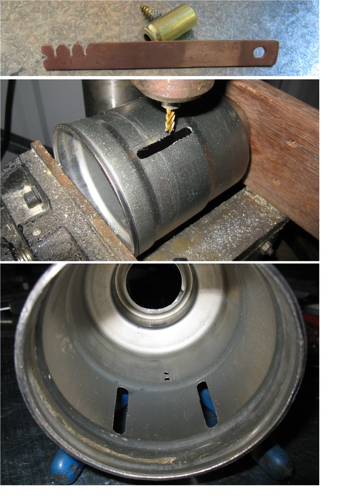
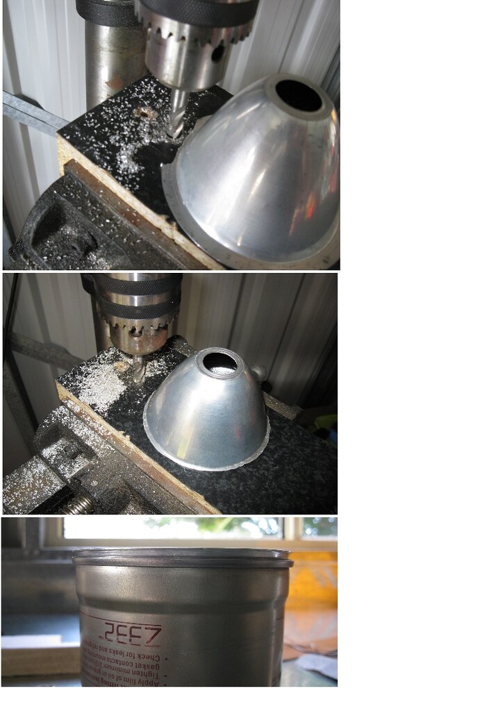
The light engine was installed in the barrel for the final time, & I set about looking for a lens. I had planned to pinch one from an old Dolphin torch, but that didn't work out, so I cut one from a thin sheet of clear plastic instead.
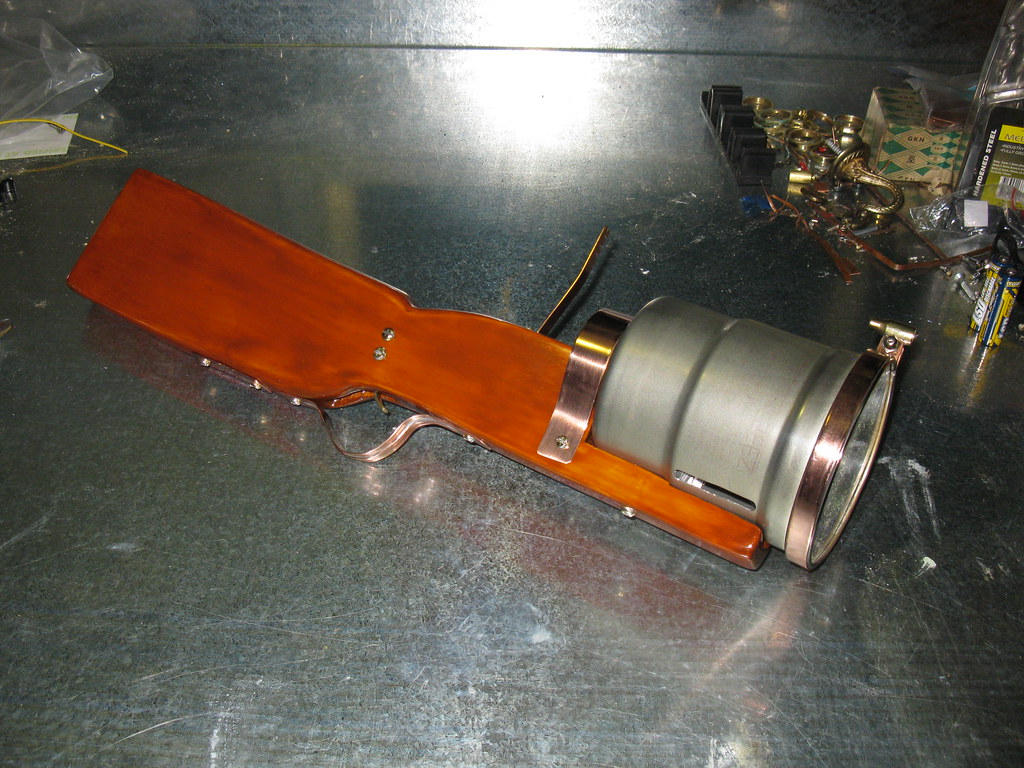
Last shot shows the completed barrel assembly, with front sight mounted.
All that is left to do now is wait for the varnish to dry, assemble the hardware, & join the wiring to the light engine.
June 25th Update
.....or so I thought. A combination of old varnish & cold weather (& maybe a little impatience) bit me. The varnish just didn't seem to be drying, & it needed sanding & re-coating again. It was like trying to sand bubble-gum... I made the best of it, & wiped it down with some turps, & finally got it smooth enough to have another go at varnishing.
Armed with some slightly-less-old varnish, & a new $2 brush, I was back in action. I applied a coat last night, & another tonight, & it's looking good.
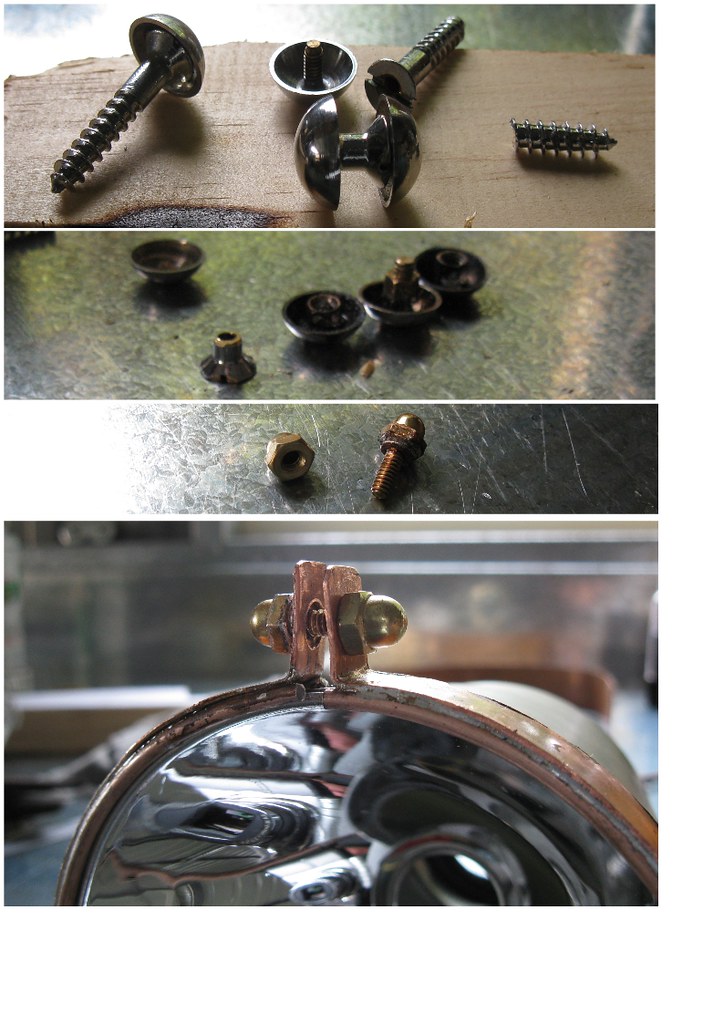
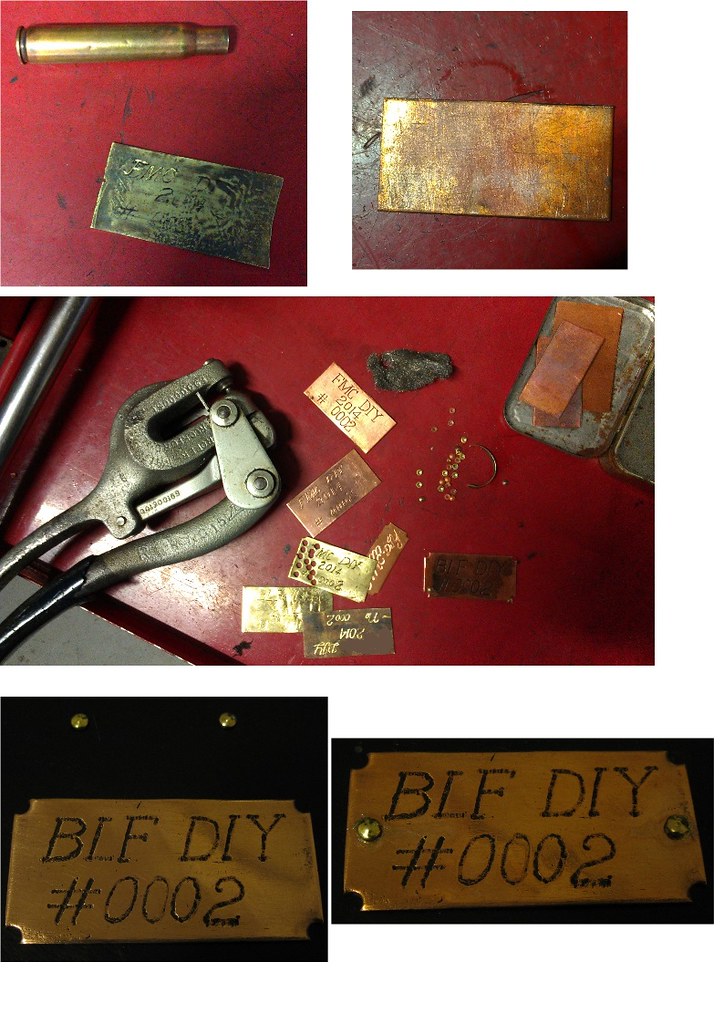
Meanwhile, all of the shiny bits have been polished up, & I also made up a little plate to attach to the side of the stock. Some more brass shells were cut up & flattened, & some copper plates were cut, & I played with a few different designs. When I finally settled on one, I made some fake brass 'rivets' with a metal hole punch, & also used the punch to trim the corners on the copper plate. The rivet heads were then soldered to the copper plate.
Here's a pictorial of the process;
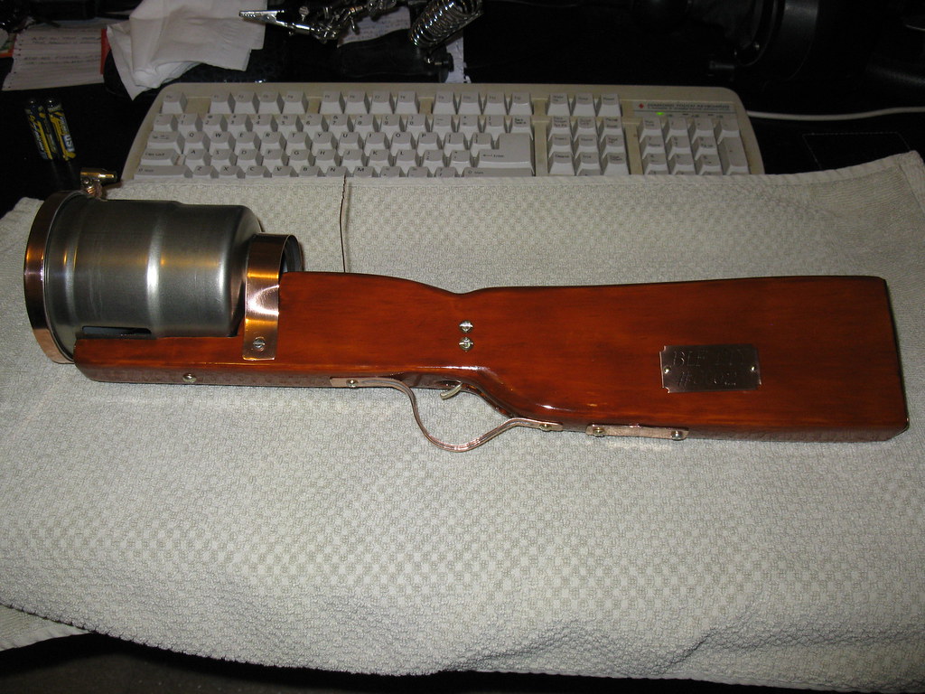
June 26th update & finished product!!
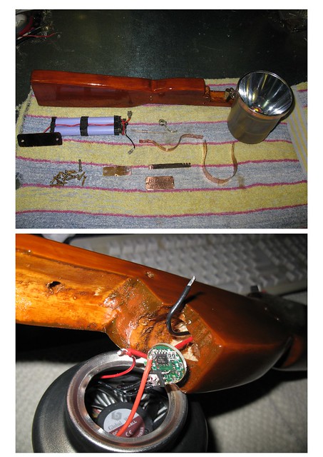
The following shows all of the pieces prior to assembly, & the final stage of the wiring.
When I was testing out the driver a few days ago, I was debating on how to hook up the fan. I didn't want it running all of the time, & didn't really want a separate switch. After a little probing, I found out that if the fan was attached to the PWM output, there was not enough juice to start it, unless it was on full output - perfect!
I slipped a length of shrink wrap over the wires, soldered it all up, covered the driver with the shrink wrap, & tucked it all back in the recess at the end of the stock.
And not too long after that, we have the finished product!
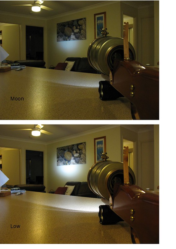
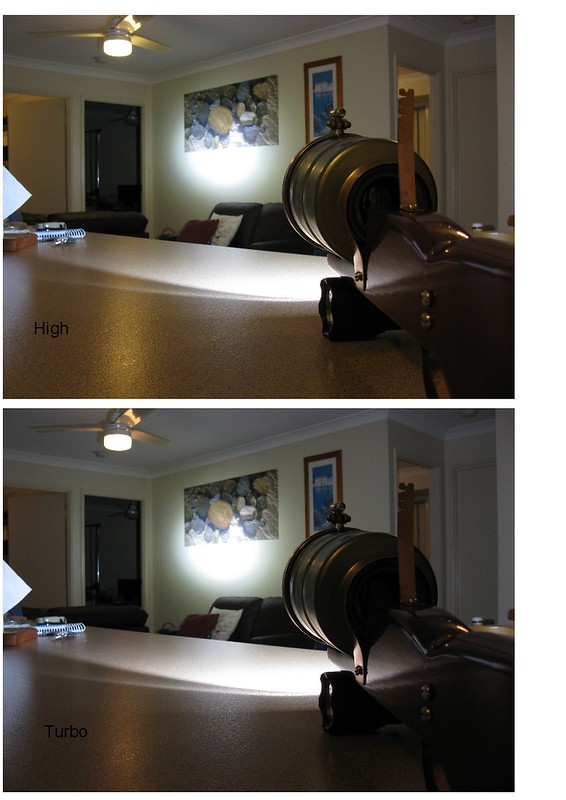
Indoor working shots - the camera was self-adjusting, so turbo looks lower than high.
For size comparison, the light that the Mortar is sitting on is a Convoy L4.
Here is a link to all of the pictures in Flickr, for those that are interested.
Short video of operation;
https://www.flickr.com/apps/video/stewart.swf
Beam shot comparison
I took the Mortar into work today to show the fellow workers, who all loved it :)
For comparison, I also brought in the following lights;
* HD2010 w/ XM-L2 U2-1A Original East92 driver, KK ICR 26650.
* Convoy L2 w/ XP-G2 R5 , de-domed, @ 5A
* C8 w/ MT-G2, modded 12*7135 Nanjg.
I'll show some mouse-overs for each light, comparing it with the beam of the Mortar.
"The Crow-Tree" - a little over 100 meters distance.
Mouse-over for HD2010

Mouse-over for L2
Mouse-over for C8 MT-G2
-------------
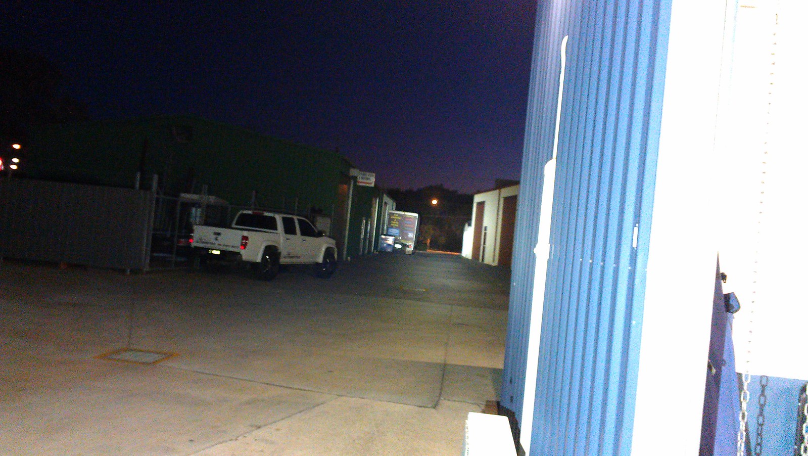
The driveway
About 70 metes in length, with industrial sheds either side.
Mouse-over for HD2010
Mouse-over for L2
Mouse-over for C8 MT-G2
Overall, I think the reflector works really well with the MT-G2. I can't wait to get some hotter cells into this light - with the shots above, it has Samsung ICR 28A laptop pulls in it, & they were nowhere near fully charged, after me playing around with it last night for quite a while, & also earlier today with the workmates checking it out.... They each found turbo, heard the fan cut in, then shined it around for a while.... All of the other lights above had freshly charged cells in them.
Build Stats
Cost;
* MT-G2 - ~$20
* Length of Pine - ~$7
* New paint brush - ~$2
* Brass screws - ~$8
* Reflector - ~$3
The rest of the components I already had lying around.
Tools;
* Drill press
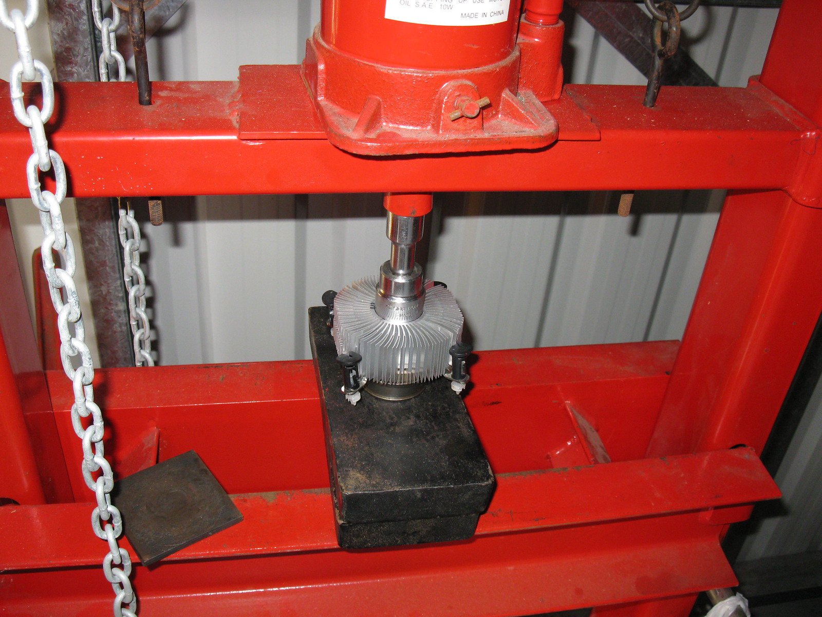
* Hydraulic press
* Grinder
* Hand drill
* Various files
* Hand saws (wood / metal)
* Tin-Snips
* Hole punch
* Engraver
* Cheap Butane torch
* Soldering Iron
* SOIC clip & AVR programmer for custom Nanjg driver
* Screw drivers
* Hand chisels
* Thread tap
* Hammer
Time Spent;
Invaluable! :)
Thanks for reading - it's been fun getting this thing together :)
--------------