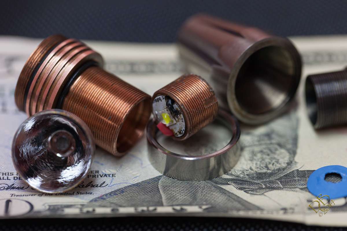
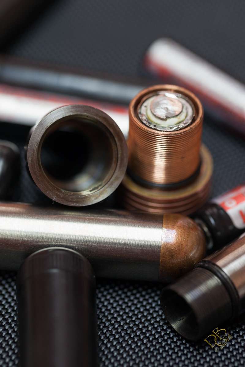
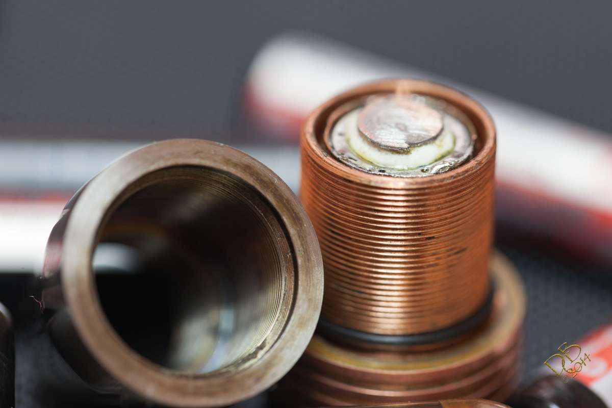
This drivers pcb is thinner by almost half than the prototype PICcolo driver. So it sits inside the copper pill which worked out really nice, allowing me to solder the ground ring to the wall of the pill pretty easily. I used Rufusbducks sandwiching idea to pot the top side of the board with Arctic Alumina Thermal Adhesive and placed a disc of copper for the battery positive contact right on top of the small FET, pressing the AATA to a thin layer between them. With the power lead coming through the board, I simply stripped the insulation, twisted the wire, wrapped it around the copper disc and soldered it in place. Then sanded most of the solder off so the battery has as direct contact to the copper as possible. The AATA was white and shiny, til the flux made it ugly. Oh well. Not like it’s seen other than here.
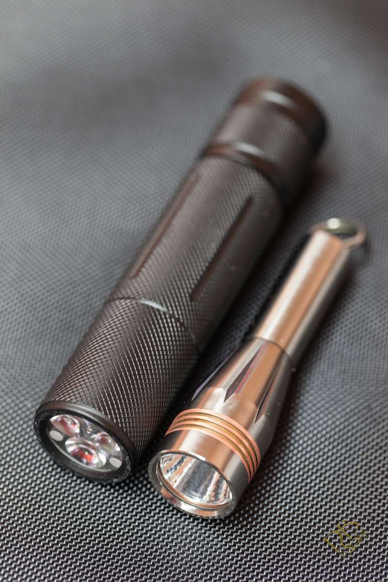
As you can see, in spite of Comfy’s efforts to make the Convoy S6 ultra small, the Texas Poker is tiny beside it. Sure do like seeing those .5mm threads all over the place! Especially in copper…. ahhhh :bigsmile:
LOL ;) I didn't try to make the S6 ultra small, I just tried to get rid of the wasted space in the existing design. It's practically a baseball bat compared to others...
I was making reference to the fact that the S6 I showed the TP next to wasn’t stock. Probably should have put a stock one next to it, or showed it next to the S2200. lol
I could’ve shown it next to a mini C8 and made it look big… it’s about the same size as the mini C8 and without looking close it would have looked full size.
Dbcstm, you can clean it up with rubbing alcohol and a toothbrush. B-12 works faster but is much more toxic. Neither seems to affect the solder mask or silkscreen.
I just built the second BLF Tiny10 FET. :bigsmile: It’s running 3.48A to an XM-L2 T6 3C. I’m either going to hook it up to a de-domed XP-G2 R5 1A or a domed XP-G2 R5 3C. Whatdya think?
The little 3” Texas Poker is now doing 552 Out the Front lumens at start up, 452 at 30 seconds. Pulling ~3.02A from an Efest IMR10440. De-domed XP-G2 R5 1A.
BLF Tiny10 FET with 22 ga Silicone wires. No limits in the firmware.
Nice! I did get access to some lab power supplies so I have been playing around with XM-Ls at sub-zero temperatures (peltier plates and dry ice); it got brighter all the way up to 9 amps. Someday I’m gonna get set up to measure lumens and redo that experiment and see how many lumens I can hit with an XM-L.
No problem, if they work without them the gate resistor can just use a jumper.
Is it possible the longer trace on the SRK board is why those don't need the resistors? I really can't come up with anything that makes sense to explain it. :~
I don’t know about dissolving fiberglass since it’s resin and fiber but you can sand it thinner. The more common way of doing it so far has been to drill or machine out the center pad and replace it with copper.
I’m amazed at how close the components can be on the driver and not have issues. Some are difficult to see if they’re not touching, they’re that close. And yet some pretty major amperage runs through the circuits and all is well, and with these little bitty drivers the traces just can’t be all that big…is 22ga wire from the driver to the emitter overkill? I had to stuff the wires into the TP pill, even had to pull em through with my curved jaw hemostats, they just do fit, like everything else on this driver.
Most of the traces only carry signal currents and on the Tiny 10 the trace length to the led pads is practically nothing. Led + is straight through the board with no trace, led- is less than 1mm and gnd is a wide tab. Lately this subject has received more attention and an effort has been made on some of the new project boards to make sure of adequate trace width. If you think it’s necessary you could scrape the solder mask from the drain trace and when you solder the FET or 7135 it would flow to the - via. If it is an issue then that trace width could be increased but that driver wasn’t designed with 10A currents in mind. Wire size is a different matter due to increased length but at 2A awg24 will only drop .017V in 1/10 foot(1.2”).
Mine’s working fine and I’m loving it! Was just stating how impressive they are.
And yeah, keeping the battery size in line with the driver size there seems to be little to no issue of power handling. 3A with a fresh IMR10440 is ample, and of course that falls with the deteriorating charge level. On a positive note, the more the cell drains the slower it drains, right? lol
Seems to me that with the way mine’s running, Turbo should deliver around 15 minutes, High should make about 30 minutes, Med around an hour and Low around 10 hours. Give or take.
That being said, ain’t no way it’s gonna run 15 minutes on high! Something would melt…