I generally think through as much as possible before I start a mod but I don’t figure everything out and often don’t even make any sketches. Other than the concept sketch there were no detailed drawings of last years project and there won’t be here either.
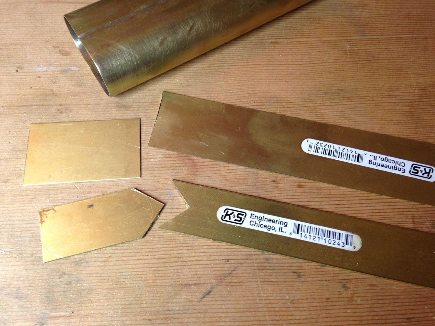
I want the battery tube to be short and not overly large in diameter. In fact, what feels comfortable in my small stubby hand (keep it clean folks) is a side by side 2x 18650 with fairly thin walls. Also I don’t want a tail cap switch but a thumb switch located right under my thumb. When doing demo I get to dismantle a variety of copper and brass fittings and thought these would be good parts to use for their corrosion resistance(at least the brass) so I started with a short piece of waste and overflow from a tub drain. Using a piece of wire to measure the circumference of both the 1 1/2” brass tube and that of 2 cells I figure I can remove at least 1/2” of material and still close the tube over the cells. Here is the tube being cut.
After annealing the cut piece and flattening it a bit I used a strip of brass to mark my 1/2” cut. This same piece of brass will overlay the seam when I braze it.
I masked the part I wanted to keep.
And spent about 20 minutes with the Dremel making the two cuts.
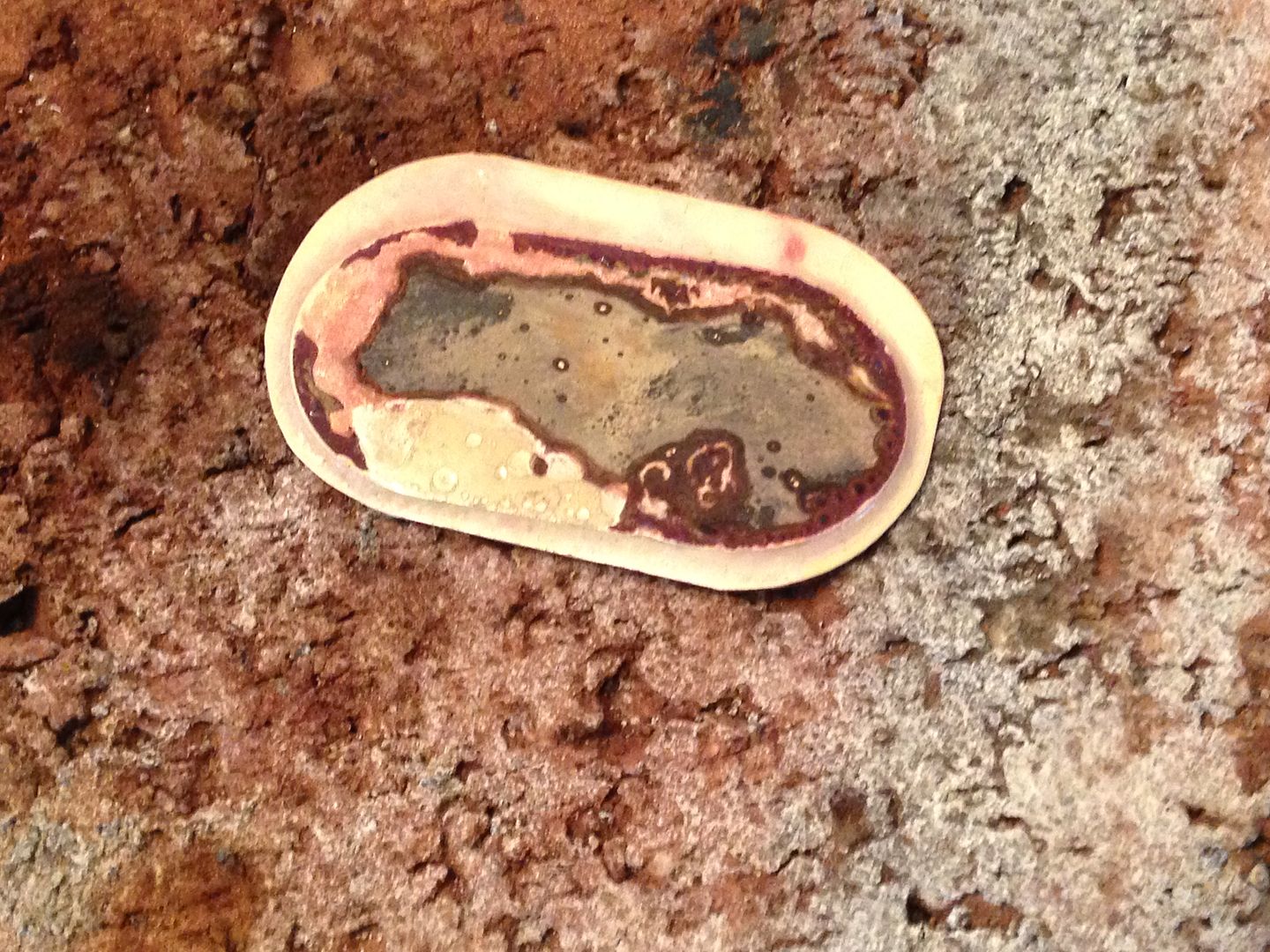
After several hours of painstaking work heating and bending the metal I got it close to the shape I wanted but started noticing bits starting to flake away. There was just a tiny one at first but by the time I was ready to braze it it looked like this.
Not so good for something that might go to 4 x atmospheric pressure. A bit disheartening but that piece was obviously old and poorly made to begin with. The walls were of uneven thickness which made it very difficult to bend in the right places and keep straight in others. Then OL posted about his travails and I didn’t feel so bad. In any case I had no option but to forge ahead and start over so I cut another piece, removed a strip, and started bending and heating again. This piece, while being a bit thinner is of an even thickness which made it a much quicker job to get it ovalized. I’ll post more pics this weekend hopefully of a successful brazing operation including an explanation of that small red “x” on the overlay strip.
Edit 4/23
That weekend and one or two others came and went. I spent quite a bit of time getting the tube bent just the way I wanted so it would easily fit the cells without too much excess space.

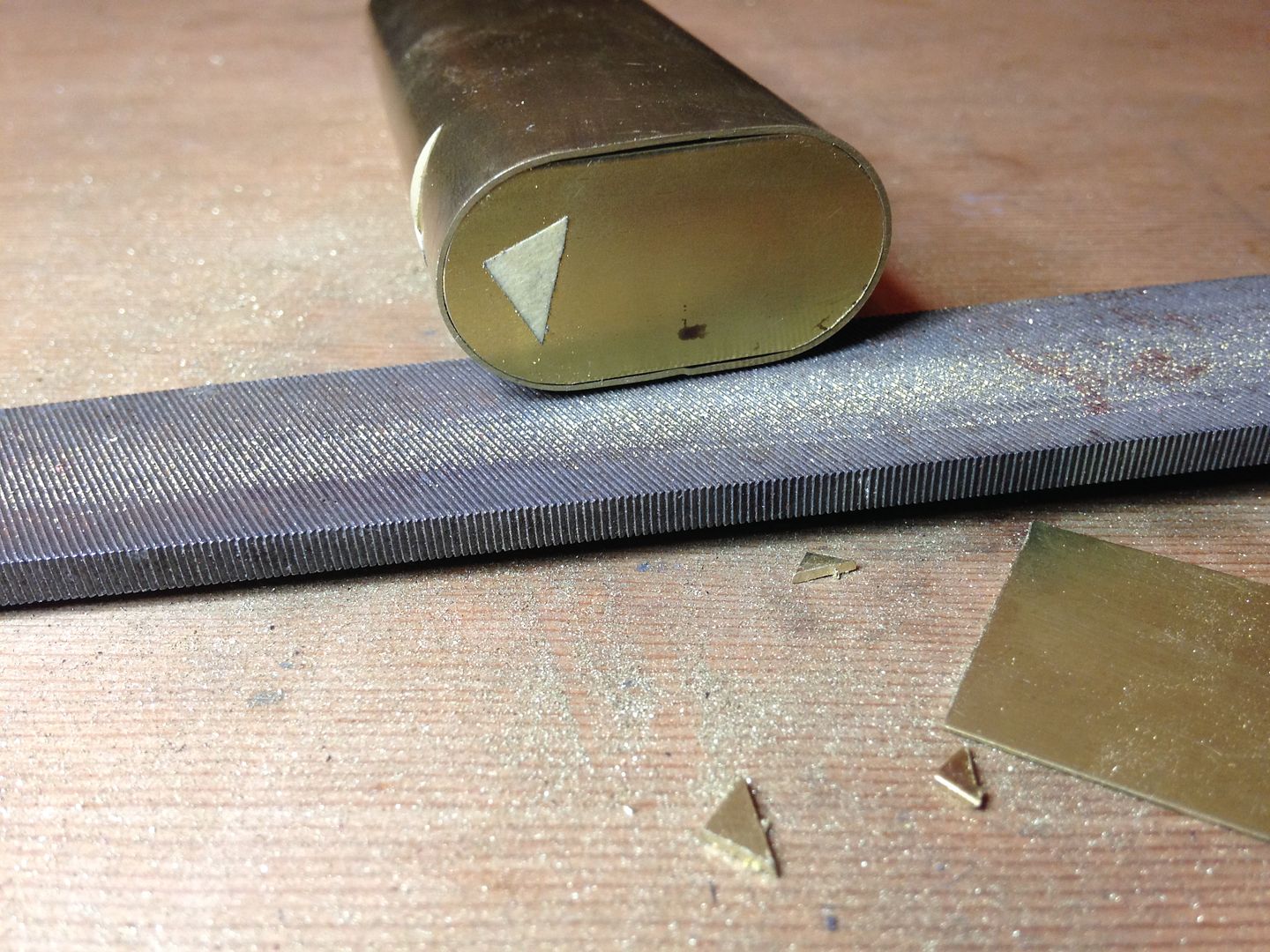
To get the final dimension just right I put the cells inside and twisted a loop of wire around each end and scored the overlap with an exacto knife then cut the last ~mm off with a Dremel wheel observing through my magnifying lamp. Then I used a flat file in the seam to dress the cut and some w/d paper to finish it off.
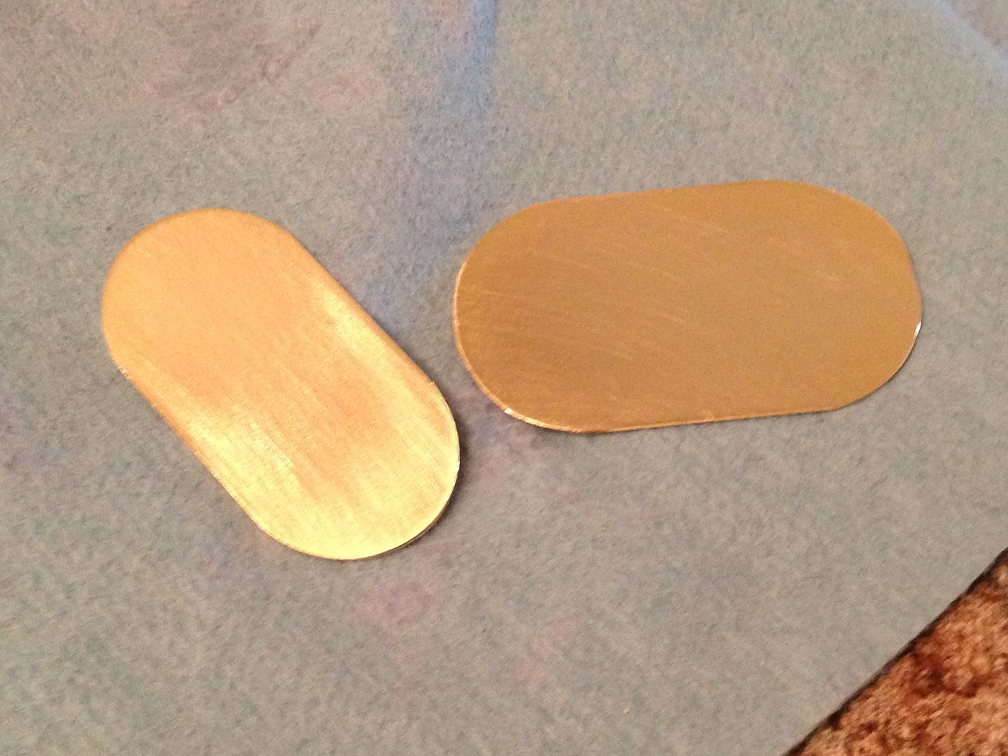
Then I pasted the seam with brazing flux and twisted copper wire around it to pull the seam shut and hit it with a mapp torch with the part sitting on a brick. After cleaning it up and a bit more time squeezing and bending and rolling a pipe in it it looked like this.
Not bad for hand formed. The bottom will be the easy end and I’ll do that next. It will be one oval piece that fits inside and another that laps the end of the tube.
05/04
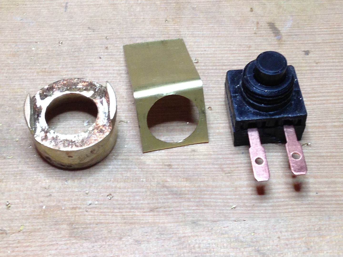
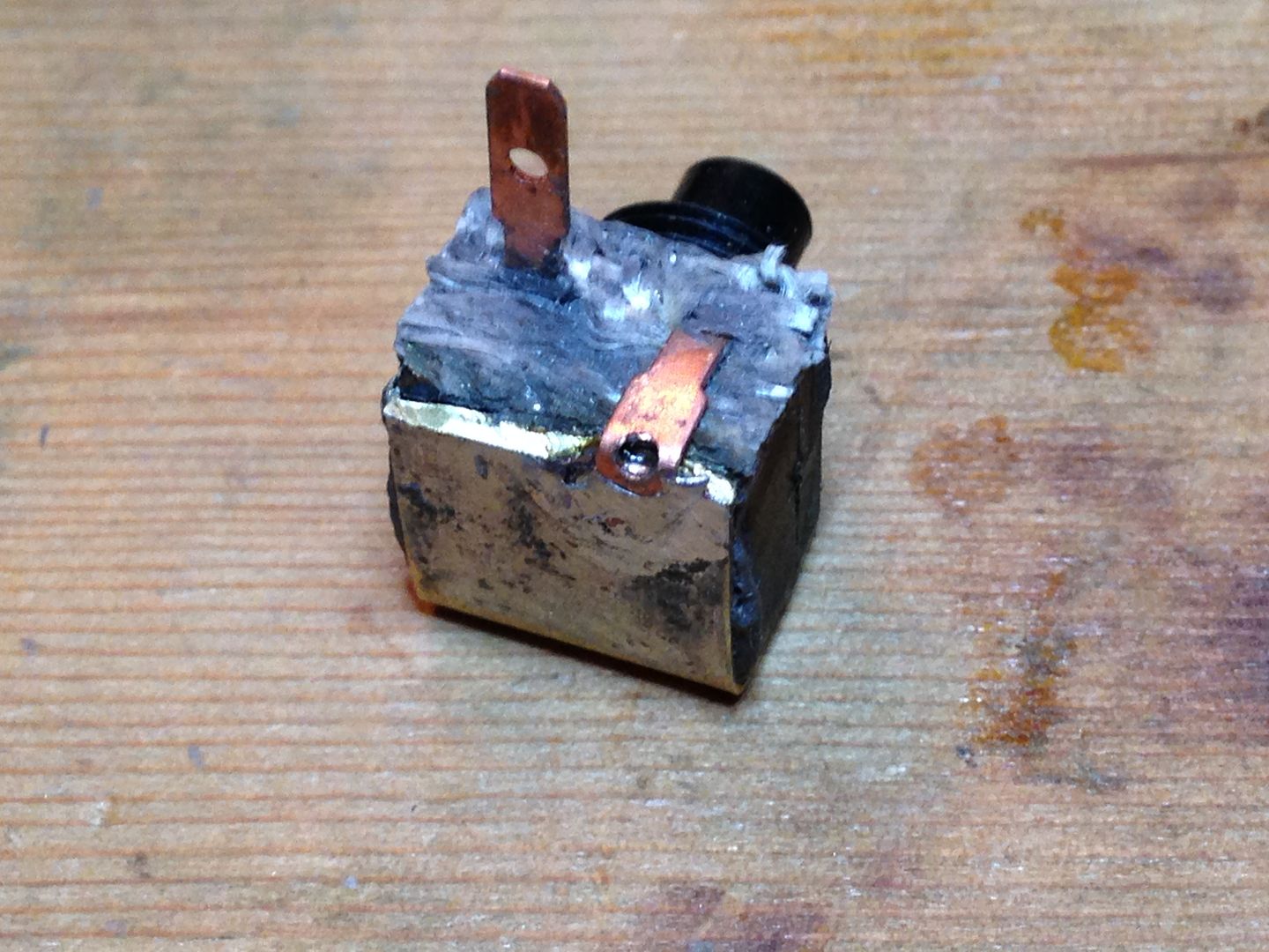
After brazing the head end on I worked on the switch. I’ll be doing OL’s mod of a 10A Judco switch. Here is the switch and boot with the switch pried oped.
And here is the drilled tube and some of the parts. I taped the outer curved piece to the inner stock and sanded the profile with the drill bit/sandpaper method.
The boot is a perfect fit for one of these thin brass tubes so I drilled a matching hole in the tube and cut inner and outer pieces from the next larger size tubing and fitted them to the curve.
There is a doughnut disc and another short piece of tube that the switch will fit into. Before I solder this into place I’ll need to make a contact plate and ensure I can fit it through the cap hole. That’s all for now.
05/05
Did some more work on this. After one false start that destroyed some of these parts.
I started over being a bit more careful with the heat on This thin wall brass. To braze, the metal needs to heat to red-orange before the brazing material melts and it’s easy to over heat and melt the parts if the flame is too close. If I didn’t need to notch this for the switch, brazing would not be necessary but if I just soldered it then it would fall apart when I solder it into the tube.
From the top. 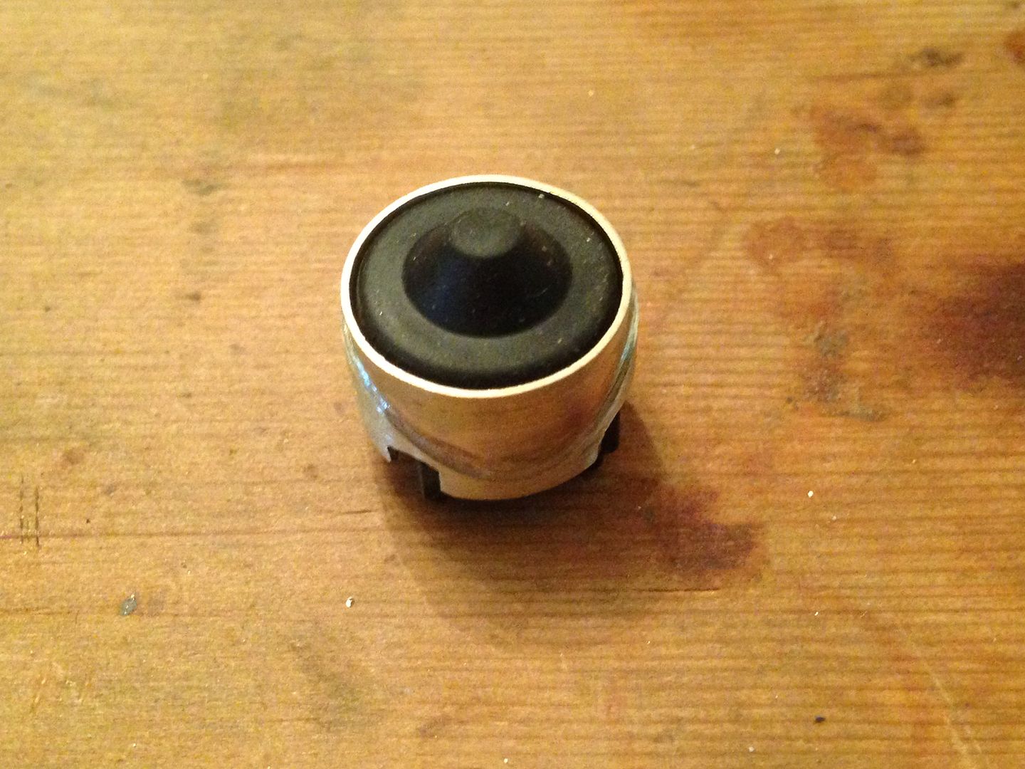
As soon as I fit a contact plate to the switch I can solder this into the tube with the other curved piece on the outside. Getting the switch into place through the battery hole will be difficult.
As I mentioned above, I followed Justin’s lead on modding a Judco switch but I’ll add these two small tips. Drill a hole big enough for the button and work the switch upside down and lay something down to support the contacts. 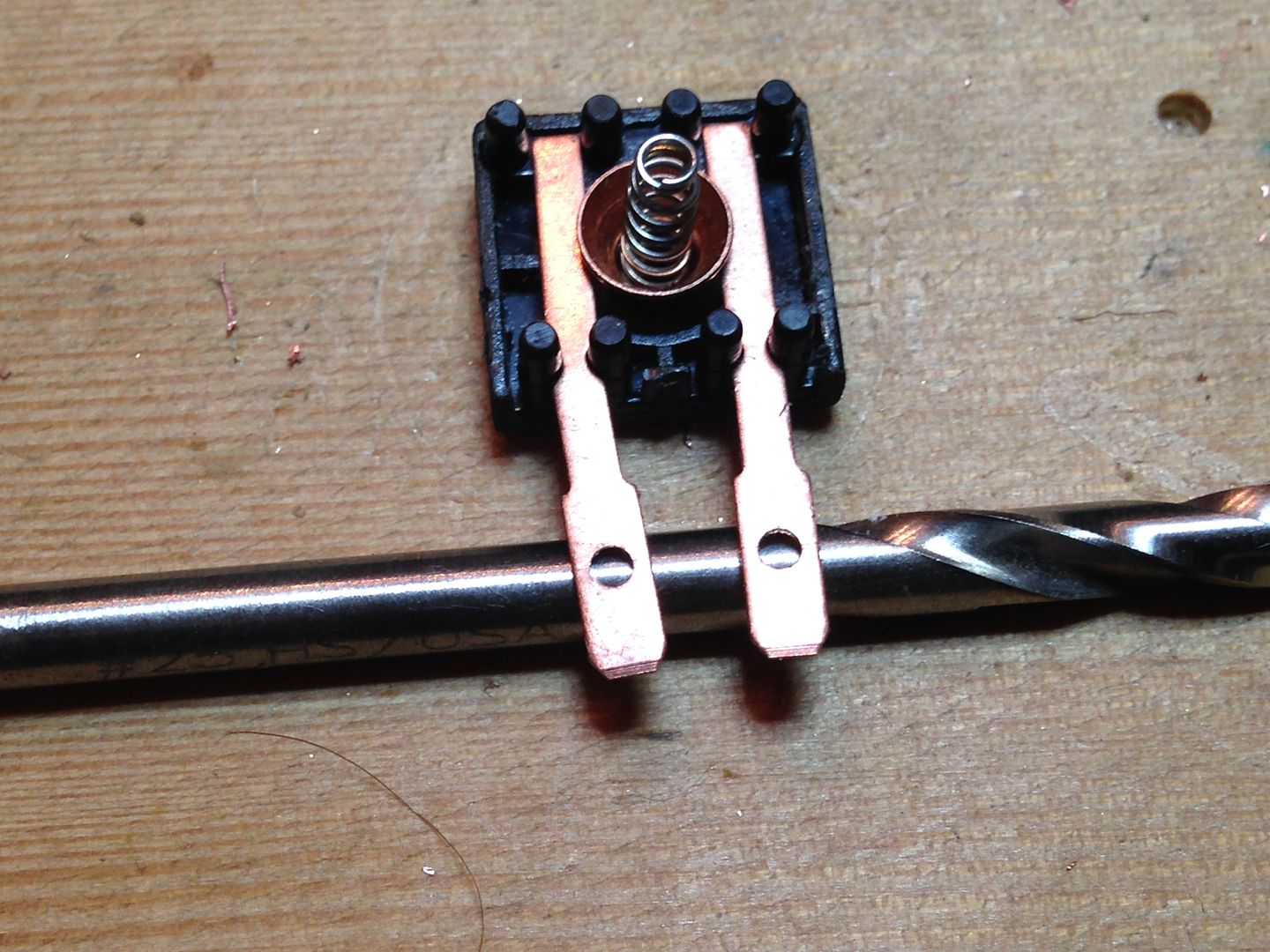
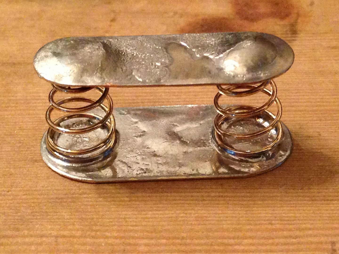
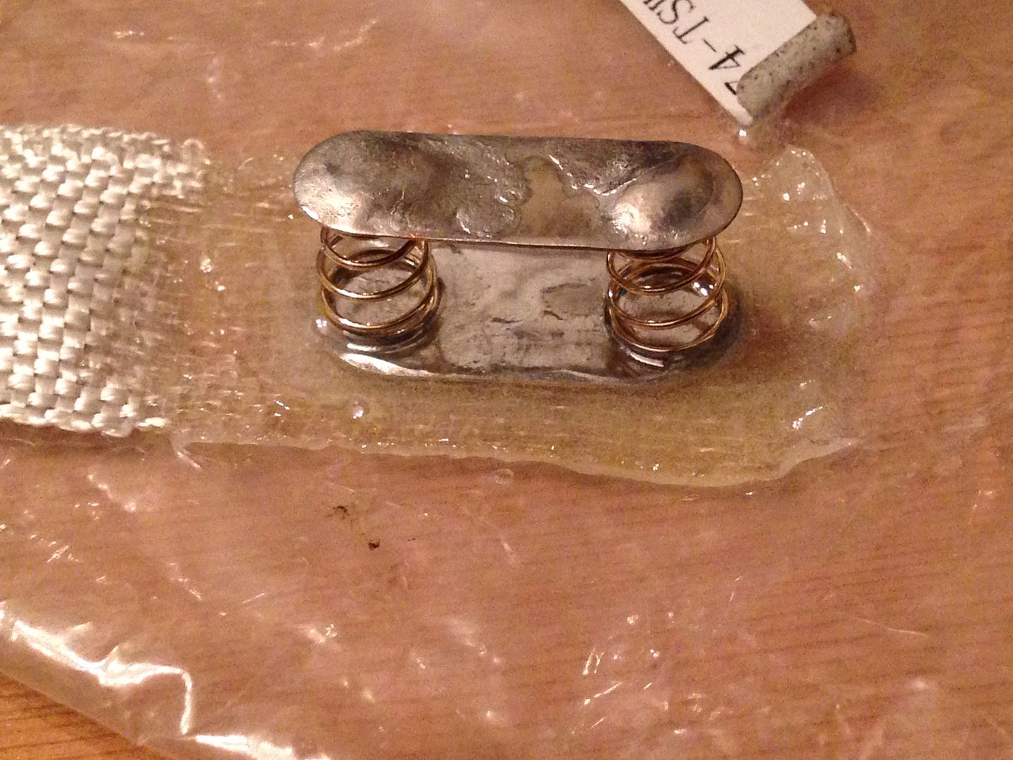
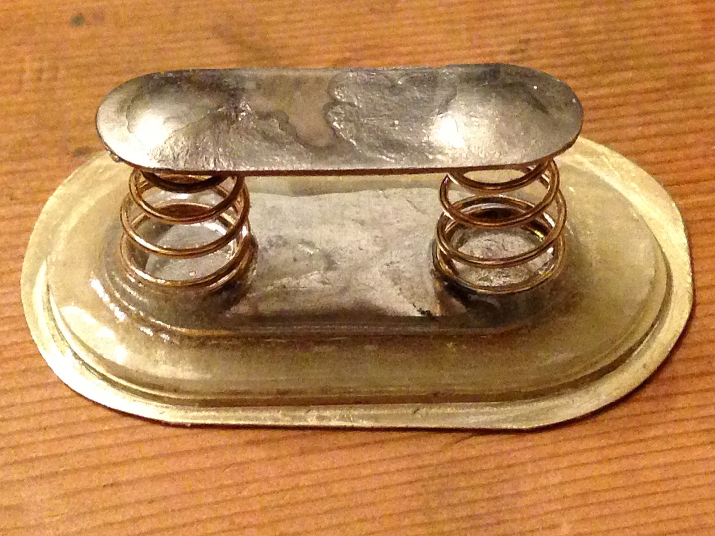
I’m concerned about water pressure on this switch since it’s a reverse clicky, any movement of the button and the light will turn off. This 10A switch already has a nice stiff spring but I’m preloading it a bit more by putting a spacer at one end.
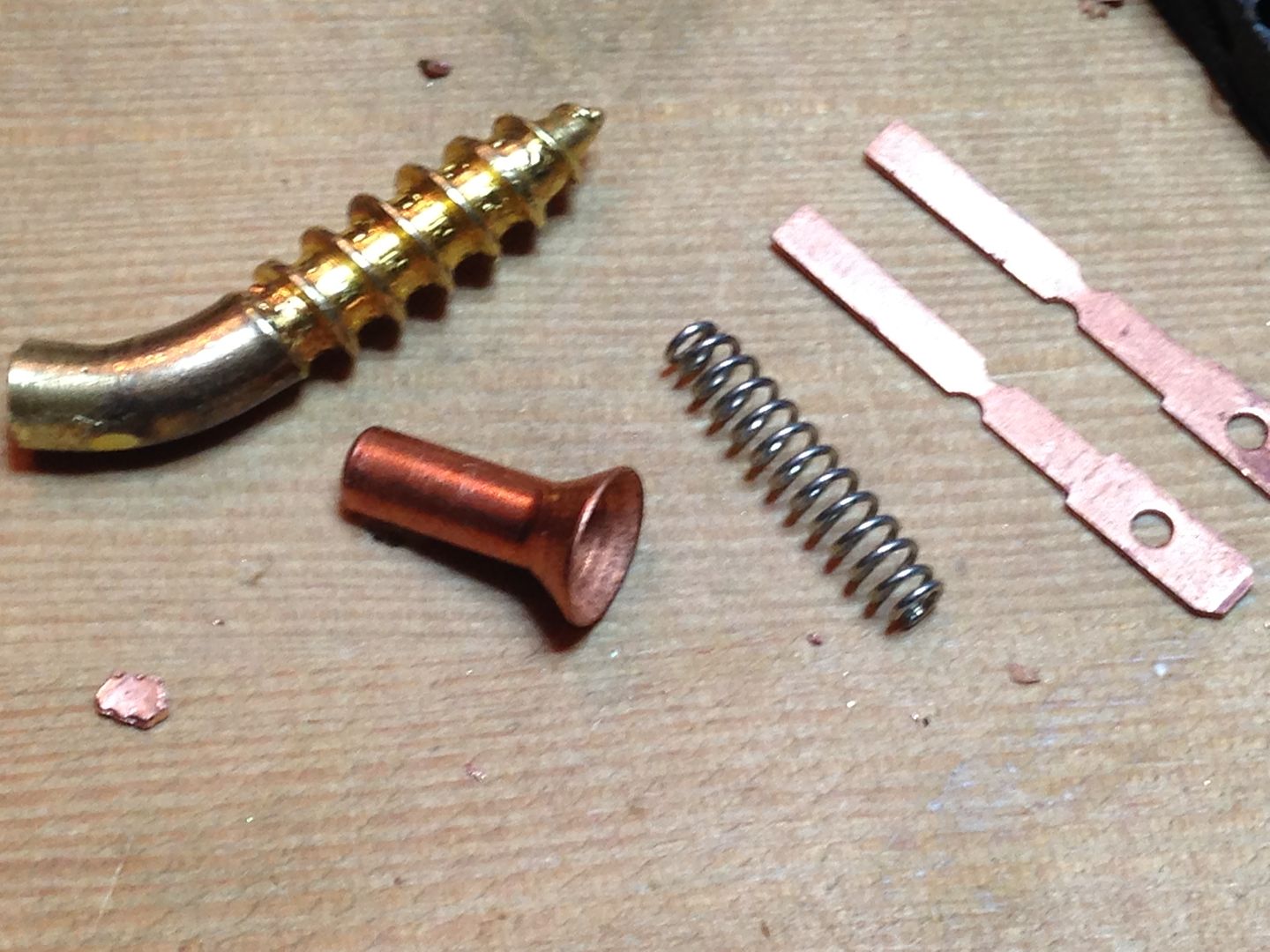
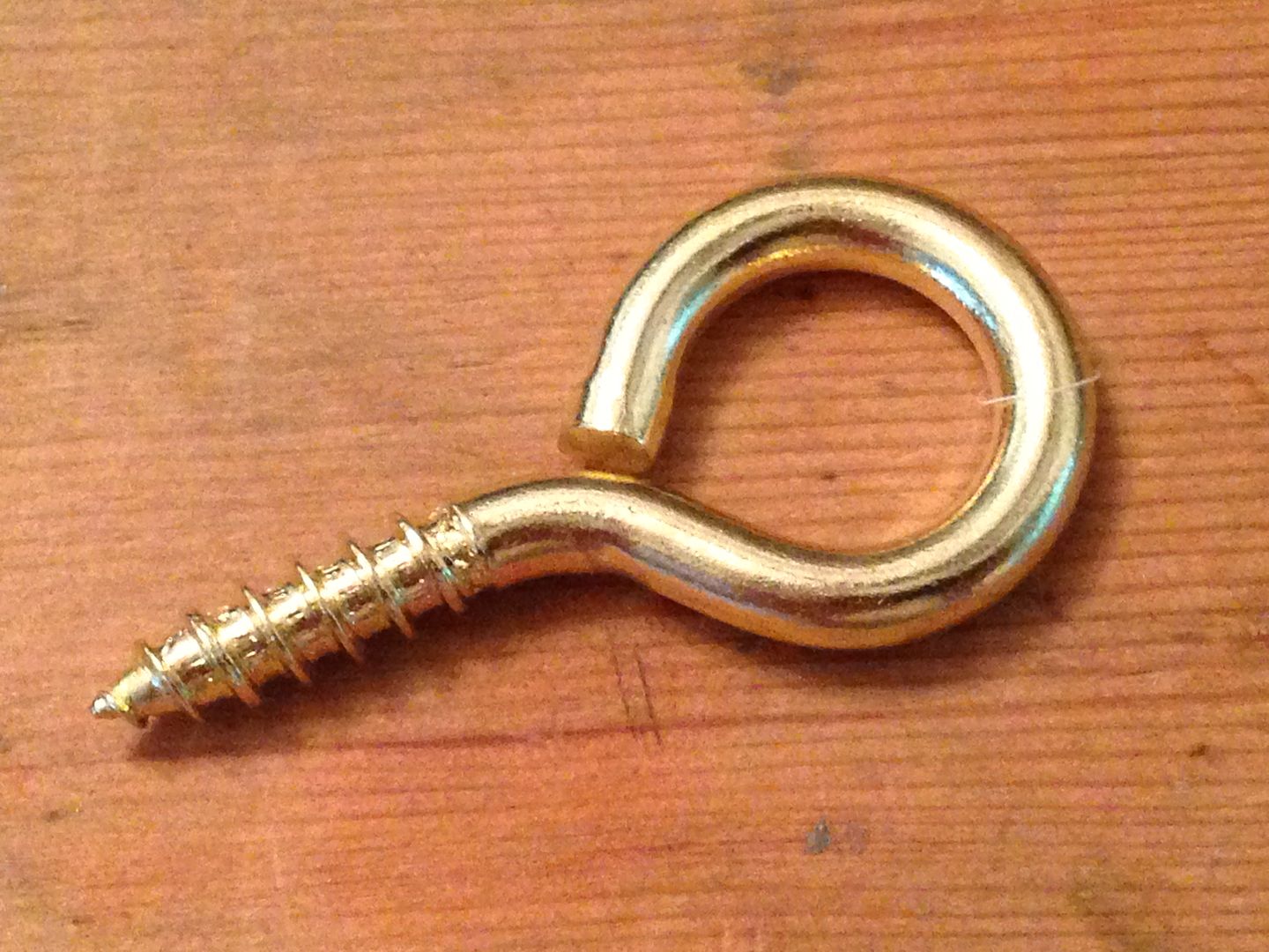
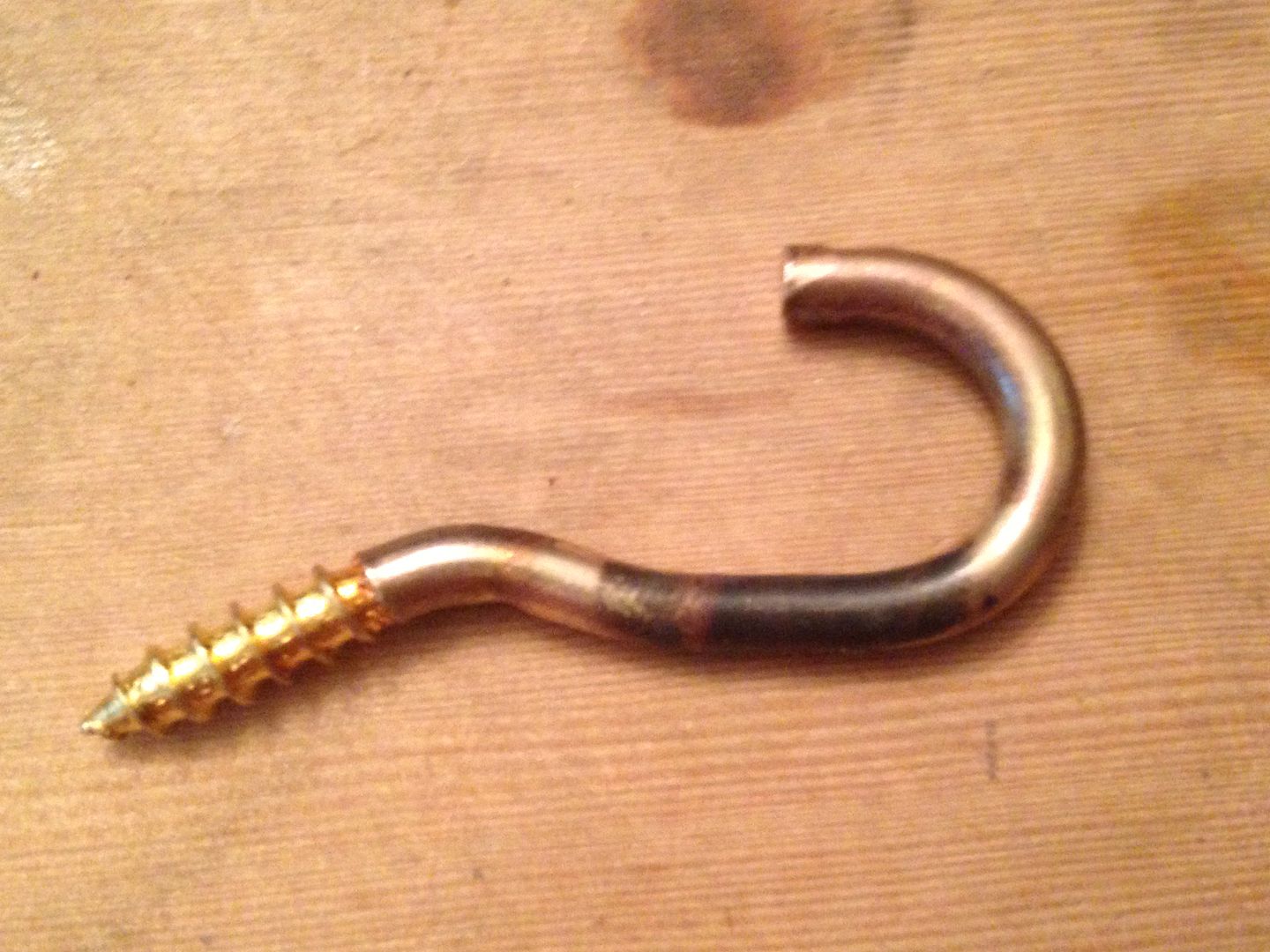
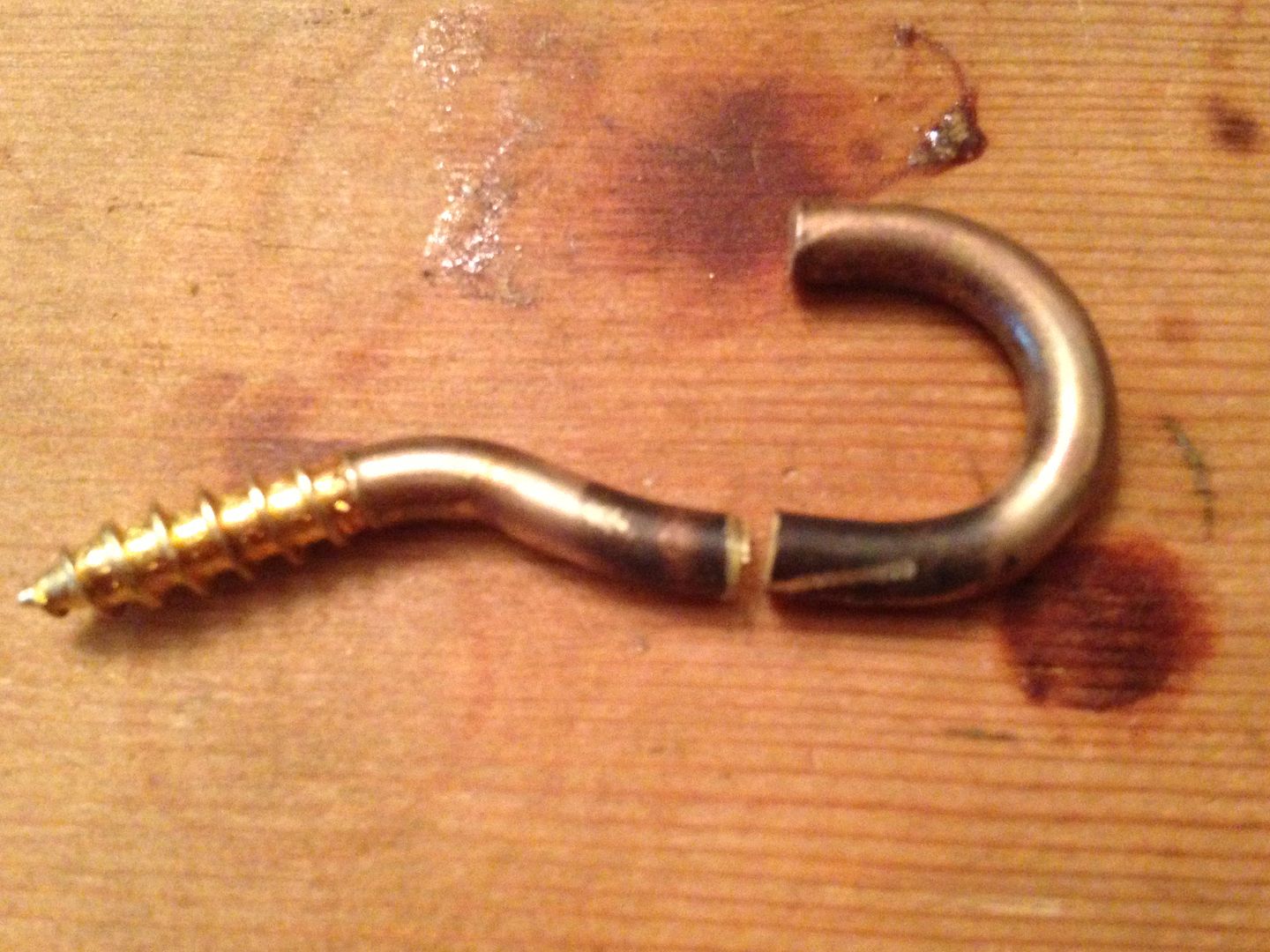
That tiny bit of copper lower left was the first try but being only .5 mm thick it didn’t do much. Next up was the brass screw eye leftover( got my money’s worth out of that one!).
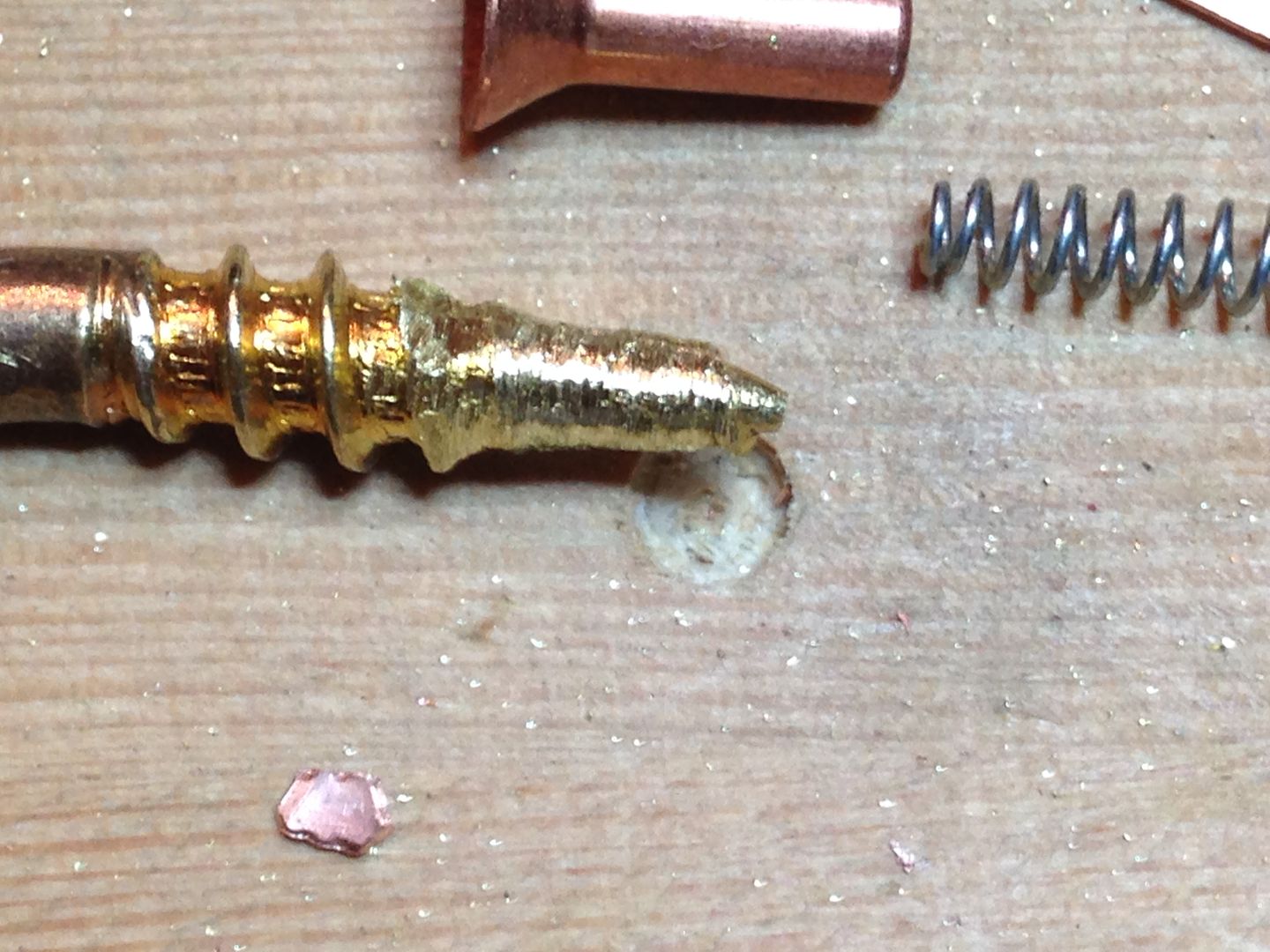
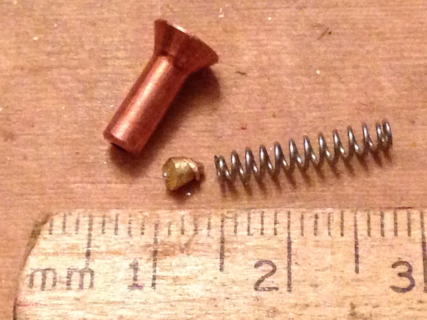
2 mm proved to be a bit too much and the switch wouldn’t “click” so I pulled that bit and cut another bit of copper from some scrap ~1.2mm thick and that did the trick. Won’t know til I get wet if it’s enough but first dive won’t have live cells.
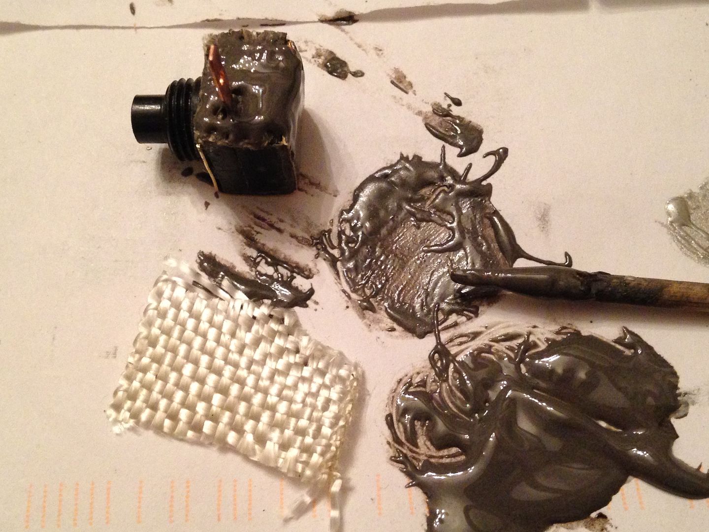
Next up was the contact pad. I didn’t have a really clear notion at first but as I went along things became clearer. First was a brass strip that wraps around the switch and keeps water and spring pressure from blowing the bottom off the pins.
This was bent around the bottom with JB weld in between and clamped until set. Then the first of 3 layers of fiberglass was added.
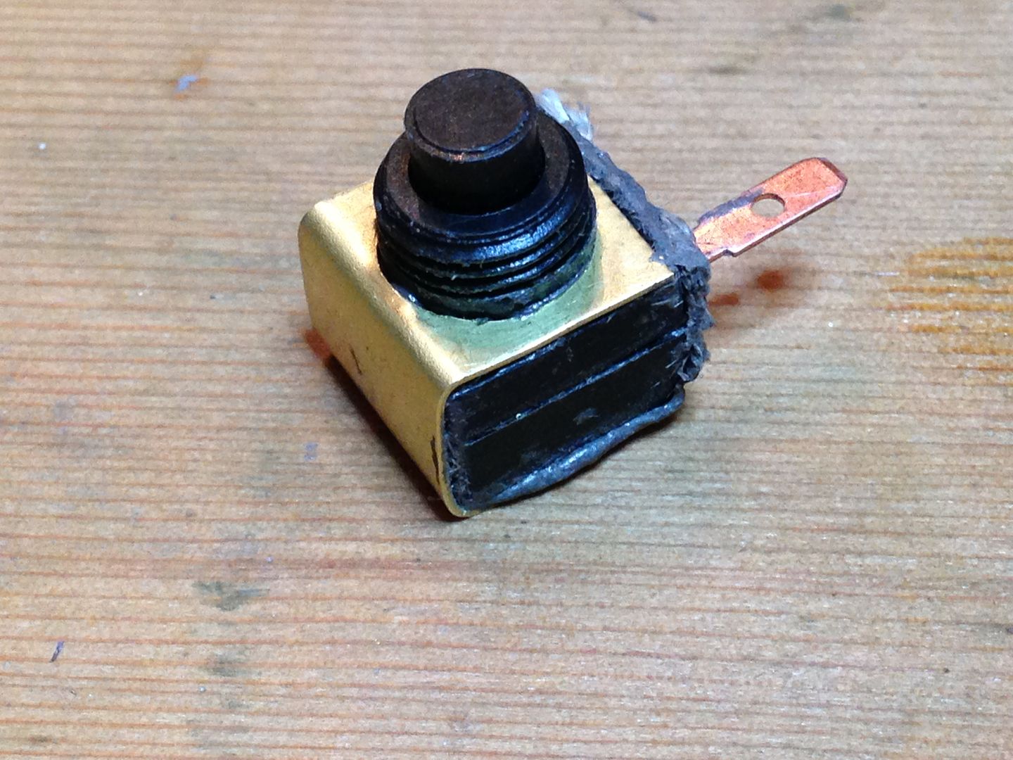
Once that cured the first of the contacts was bent into place and soldered. I had pretinned the brass previously.
This was followed by more layers of fiberglass/JB weld. This build up is needed so the battery will clear the brass switch holder and contact the pad instead.
Between layers I cut and sanded away the excess. This switch also has to fit through the same hole as the batteries and the brass contact strip will take up some space so prior to each of the last two layers I sanded the corners round as well. Here it is sanded and ready for the contact strip.
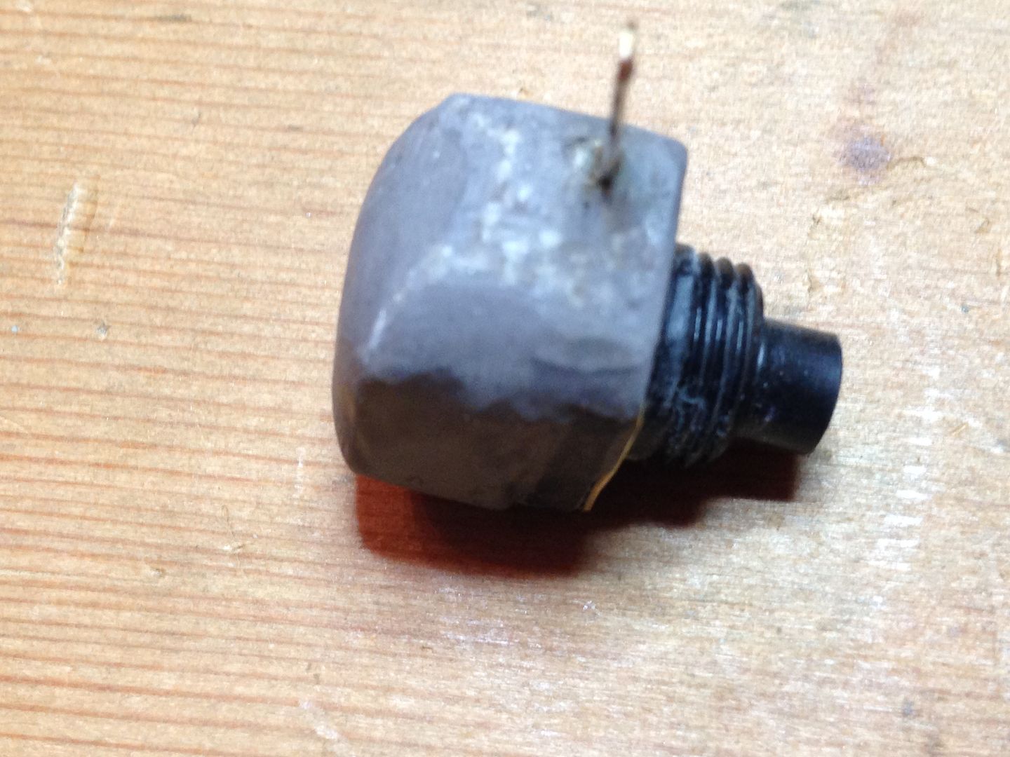
I decided to add more JB to the other end and it’s wrapped up to cure. I’ll post close up of it with the strip tomorrow.
Edit- as promised.
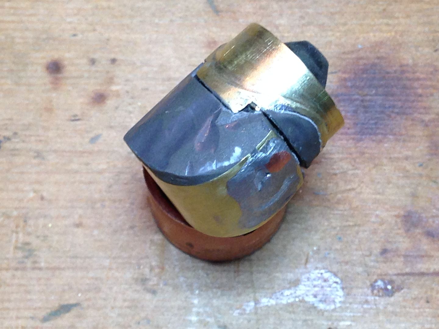
Here’s the module in the tube.
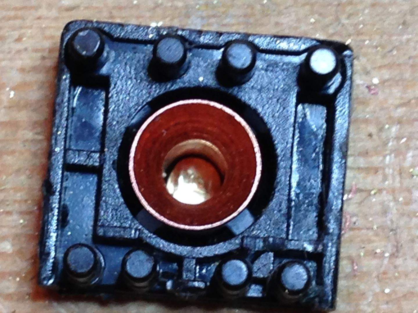
What it looks like inside. You can make out the second copper contact bent over and soldered. Since I’m using flat topped cells I did what I could to dome the brass and also added a dollop of solder and sanded that so the middle of the dome was ~9-10 mm from the tube. This pic also shows how the inner curved piece of brass fits the inside of the tube with some JB added as an insulator.
Here it is with one of the cells.
5/28
This was an all or nothing play. I haven’t tried this before and got the idea from a post a few months back of a link to a nifty looking steampunk light saber mod on Epbot. First I cut the tube to length leaving ~1/2mm or so to true up the end with sandpaper on my fir ply lap desk.
Then I cut open a soda can and cut a piece from that and also some brass bug screen to match the tube. I tried it first on the flawed first tube.
It didn’t work all that well as there were more places were the solder missed than there were where it bonded the mesh.
I thought maybe there might have been some fabricating oil on the mesh so I cleaned it first and and rolled the dice on the real part. This was all guesswork and I used up a small tube of solder paste in the process but starting with just some of the solder paste and wrapping that with aluminum(not supposed to apply flame directly to the paste) I tinned the tube. After a few of those to get the feel of it I did I it again this time with the brass mesh under the aluminum. It didn’t look too good at first but after cleaning, repasting, and reheating several times adding solder wire as well it ended up well enough to go on. I used up 2 soda cans(2 sections from each so maybe six reheats) and sometimes the solder would run out without bonding the mesh and I would have given up but had decided one way or another I was going to keep dumping solder into this #%^€?£¥$&@! piece until it succumbed to my will. I didn’t take any other pictures during the heat of battle but after a few hours not knowing whether it was working or if I had wasted a month here it is.
I’m gassed.
6/19
The Secret Part, what’s it do? Remember this pic from way back in the dim and distant past?
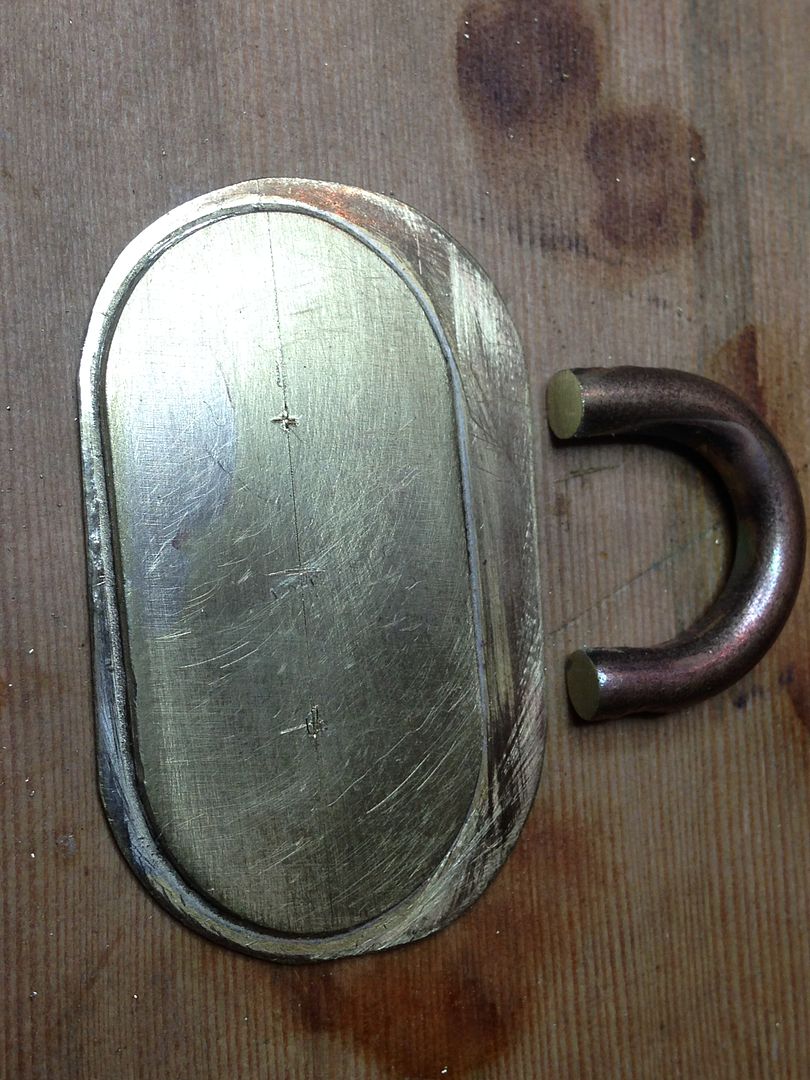
It’s the strip that originally was going to reinforce the seam but will now cover and contain the seam of the brass mesh. The “X” is where the secret lies. At the top right of this next pic you can see a phone case with a belt clip.

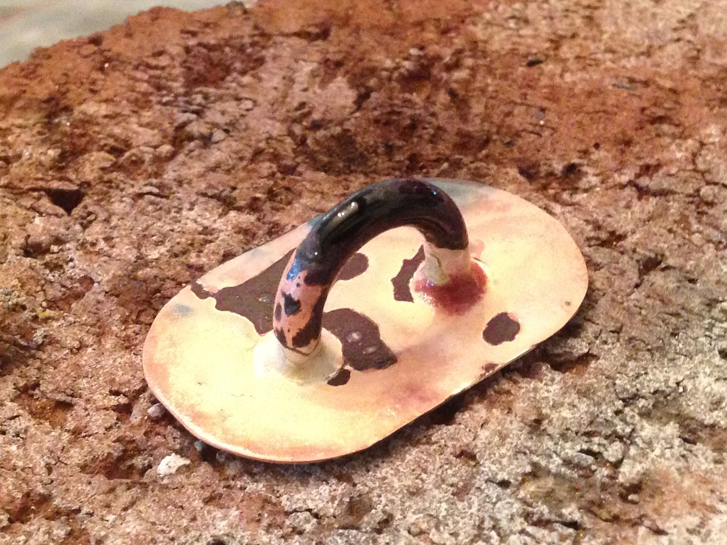
The case snaps to the clip with a disc separated from a backing plate by a short 5/16” post. I’m going to recreate the disc and post on the strip that covers the seam. The clip has a detent that allows the disc to lock at several rotation points.(the tiny grooves for that will be added later). Here is the strip, post, and disc after brazing.
On the back is another strip. You can see how the back strip fits between the edges of the mesh while the top strip to covers the edges.
To hold the strip snug into place I recovered the mesh with the soda can, laid some scrap tube on top, and wrapped it all up in copper wire.
I spent several hours chasing my tail on this as the solder tends to flow around the tube and accumulate everywhere but where you want it. At one point the bottom fell out(I should have brazed that but chickened out) and I had to clean that up and resolder it as well. Fortunately the mesh stayed put throughout the battle. In the end it was all successfully assembled.
It’s a bit ugly but still kinda cool so I can live with it. It also seems very secure. I’ll fill the tube void somehow as it would hang up on the clip.