Rufus, pretty cool setup there. I love seeing new options out there, you never know unless you try!
Does it change modes properly without the resistor?
and whine?
If it's still got the stock Qlite firmware on it (or any fast-PWM 19kHz firmware), it's not going to whine. It has nothing to do with the hardware. Even a bone stock 7135 105C will whine (causes the switch to make noise) when using phase correct 9.4kHz firmware.
Both the 2502 and this are stable using smaller cells. The 2502 up to 1.5A and and the LFPAK56 up to 3A don’t need the resistors using the fast pwm but with decent cells both need the 100 ohm resistor for stable modes. I haven’t found what the maximum current is for either but they are rated at 70A and 100A respectively. Dale has sent me a few reflashed mcu’s so I can try these out with hex file you set up Comfychair. I’ll also see what the buzz is on pwm noise. I have to transfer the test led to a 20 mm sink pad as well before I can push them any harder.
Is there a possibility of an intermediate pwm frequency?
I'm not sure that an intermediate frequency would help our situation much, well, maybe not for you old guys who have lost some of your high frequency perception  . Really though, it would probably still be audible until you hit the 18K-19K mark anyways. I'm not sure what the hardware limitations are.
At least I’ll get to experience it firsthand now and try out any ideas that come up.
I just tested my hearing limit last week in schoolclass with the pupils, and above 14kHz I hear nothing, an intermediate frequency would work for me
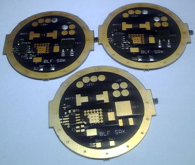
The SRK board works fine with the silent 19kHz fast-PWM. Why that same firmware doesn't work on the 17mm board using the exact same components unless you add the gate & pulldown resistors, I have no idea. The only difference is the PCB and no matter how many times I go back and compare them, they should be functionally identical, just different sizes.
I hate to say this but maybe size does really matter! :zipper_mouth_face:
Yes but remember back a ways what I found... bypassing the polarity protection diode makes the 17mm board work, without the gate/pulldown resistors. And it works flawlessly. But of course that screws up the voltage detection and it can't be reflashed unless the diode is un-bypassed. That still doesn't explain why the same diode, MCU, & FET work fine on the SRK board without the resistors. AARGH. |(
I’m still learning this whole PCB stuff, but if the board size is scaled down, wouldn’t it necessarily scale down the traces as well? Smaller traces, closer together, maybe it’s a induction or capacitive issue?
Maybe it’s an oddity of the SRK board that allows it to work rather than something about the smaller ones that is a flaw. There were simply too many posts by more knowledgeable members saying the resistors should be there. Trace length, board capacitance, signal bounce, whatever. It might need analysis with an o-scope to figure out done by someone that understands this stuff and may not be worth the trouble for us plain clothes nerds. As you like to say Comfychair “It works” either way and with the boards developed with either case in mind, just use the resistors if needed. Besides, a few months usage is not really enough time to pick up on all the nuances possible so something could easily turn up yet.
See? This is why I’m leery of opening up the Texas Poker and engaging star 2 for moon mode. Everything is working perfectly as of now, but who knows what will happen if I try that? Don’t want to mess it up…
Oh, I think GJ asked about the stars…they’re on the inside close to the MCU.
For future reference the BLF Tiny10 is set up with through holes for both led + and - so either side can face the emitter. Not all hosts use the end of the battery tube for grounding the driver but it would still be possible to have the stars accessible even if they did.
Why, I do not know. That would have made some things easier. With this light being a twisty I had to seal the board with Arctic Alumina and use a small button of copper for the battery contact, while I actually covered the electronics in full potting I wouldn’t have HAD to, with the mcu towards the battery I could have potted the mcu and still left the star’s clear for options. Never occurred to me.
I just place a small metal positive contact on top of the attiny. All pins still accessible.
10mm but its not a “tiny10”. Diode on top with attiny.

Hey comfy…I got off my duff
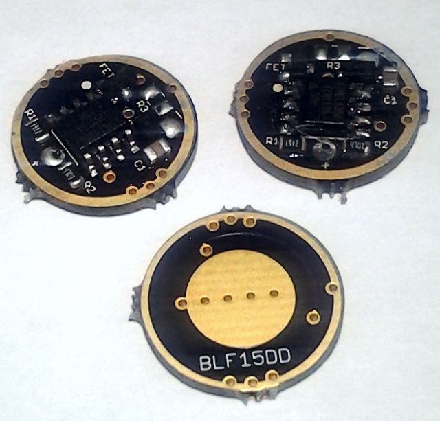
Family portrait
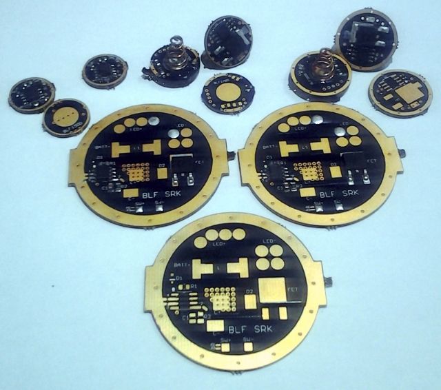
SKR FET
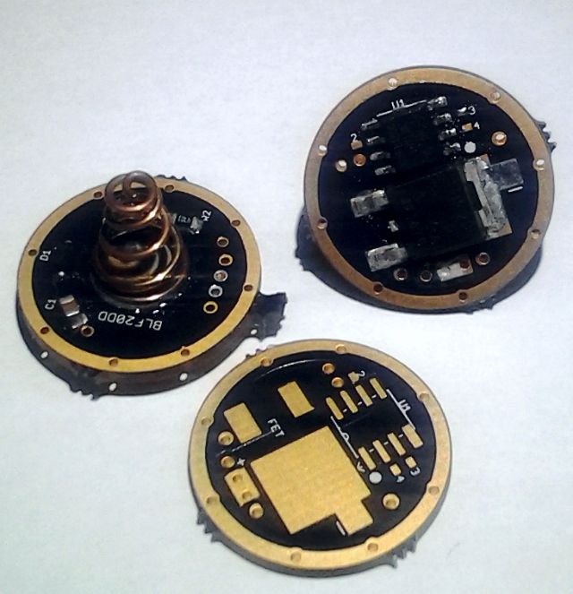
20DD
17DD
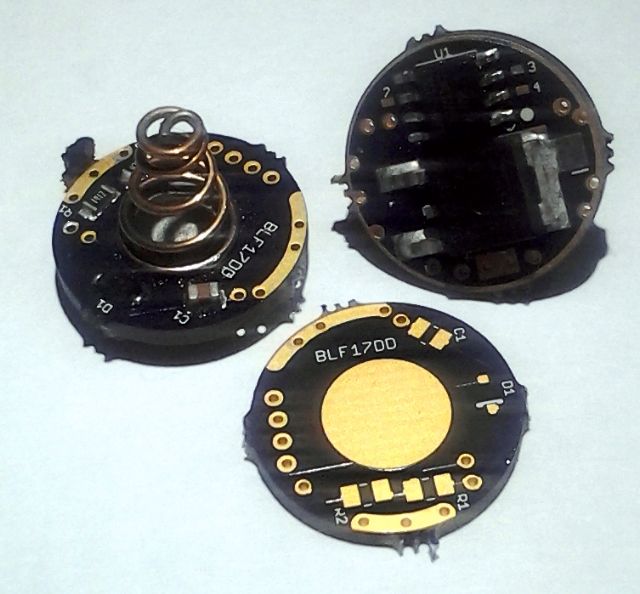
15DD
Are we supposed to jumper across R3?
Testing to come soon…just have to flash the ATtiny w/ STAR firmware and test it out
once again sorry for the ultra crappy photos
I think I got the wrong diodes, the leads go out away from the body instead of curve underneath so it made it a bit difficult to get them to go where they should go…will definitely use your buy list next time
Went thru 8 ATtinys and support hardware, 6 of the larger FETS and 2 of the smaller ones…have 2 ATtiny’s left but saving one for the 7135 SRK FET (got to order the new boards) and for another TexasPyro 20mm Nanjg (going to use 380mA 7135’s)
All in all, using the hotair rework station and manually dabbing the pads with solder paste…
I will also work on getting better photos…those are absolutely HORRIBLE!
Send me those and I’ll take some pics for you. ![]()