Those boards aren’t actually much larger, just longer & a bit narrower.
But I can’t see the TP logo on that one. Doesn’t look like the original tp4056 NanJing Top Power chip that HKJ tested. See post #43.
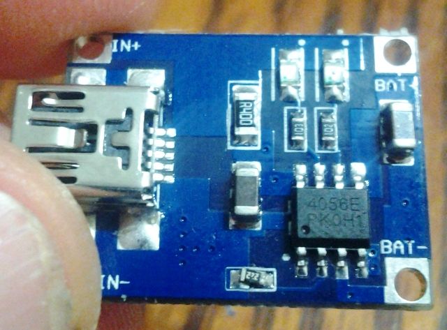
Instead the markings look like they might be 4056ES A1319N. Some kind of symbol or logo seems to be before A1319N. It could be yet another clone chip. Unless you can test it and chart its charge profile I would just stick to the original chip (stylized TP logo) that HKJ tested.
The datasheet for the NanJing Top Power chip claims a max input voltage of 8 volts so 6v should be fine.
Just connect positive from the solar panel to IN+ (next to the usb jack) on the tp4065 board, solar panel negative to IN-. Do not use the usb jack if the solar panel is connected. You could use a couple 6V300ma solar panels to charge faster. Check with a multimeter that the solar panel are actually providing enough voltage & current.
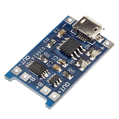
Has more components in addition to the 4056 chip, and costs a bit more. Wondering what the diiference is.
The board cuts the power at 5.5V but I don’t know what that solar panel delivers. Wonder if I could cover part of the board , if V too high, or does that cut A?
At 5.5V the tp4056 board did reduce charging current in HKJ’s tests but that was a tp4056 board being supplied with 5.5V @ more current then your 300mA solar panel. Probably over 1000mA.
At lower currents it shouldn’t heat up as much (it gets rid of extra voltage as heat) & shouldn’t need to reduce its charge current.
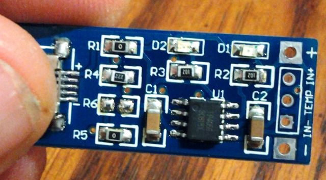
The 2 extra components are just jumpers. Marked “R1” and “R5” in white text on the board. Marked “0” on the components. They are jumpers / zero ohm resistors.
There is one thing this board does provide that the other one doesn’t. It has a point to connect to the TEMP pin. Requires extra components to actually use that though. NTC thermistor & a proper resistor to set the temperature cut off.
Thank you for the all the information. Would be interesting to set one up to shut off at a certain temperature.
Thought about it, It makes a lot more sense to start out with a couple solar panels and see how it goes. I might start with 2, if I get 250 ma or more, maybe just connect one. If I get less than that, maybe 2 in parallel to double it. I could leave it outside, I suppose, as long as I shaded the board & battery.
How much amperage could I run through this? Saw 1200 ma in the data sheet, although it might be hard to keep cool at that, especially over 5 V.
Actually when I reflow mine (I have a hotair rework station) I just snag the old RProg resistor off with a pair of needle nose tweezers, then lay the replacement resistor on the pads, there is enough residual solder for it to stick and bond no problem.
Also gotta be careful with some of the square TP4056 boards [longer rectangle ones seems 0805 standard], the RProg resistor is a 0603, the 0805’s will fit but you have to be a bit more careful on placement
This is the board I changed for fellow board member woolfam, not the most beautiful solder job, but I tested and they too were pushing a clean .53A and .48A respectively with a 222 resistor on RProg
Changed the 122 [1.2K resistor = 1A] to a 222 [2.2K resistor = 500mA~] Tested, was pushing .53A to a 3.6vdc battery out of the USB module into a repaired Xtar MC1 slider housing
I can confirm at 1A charge the TP4056 gets VERY hot, burned my finger when I put it on it to see how it was doing, at 500mA…warm but not leave a mark on my finger.
WarHawk, I see two different “4056” chips. Love how china makes clones of clones. Might want to check the current a few times throughout a charge cycle. Check that the current tapers off at the end & appears to do some kind of cc/cv. Also that it terminates well without trickle charging.
I had an unmarked 4056 clone that was trash. No attempt at cc/cv. Over 4.27v.
Perhaps these “4056” clones should get a separate thread since they are not the chip HKJ tested.
My solar cell arrived yesterday. Got 7 V and 350 ma with direct sun& haze seems to be charging now!!!
I soldered leads to the board and solar cell then attached the wires with alligator clips. Should make it easy to put it back in mini USB 5V.
My board has no logo. Seems to work OK but cuts off around 4.10 V usually.
A US penny will fit on the back without touching any connections for heatsink. I just alligator clipped it. Didn’t seem to need it though. Didn’t sand. Only got up to 550 ma or so on mini usb. Assuming i measured it right, 850ma listed usb oem phone charger.
A friend told me solar runs off IR, which gets blocked by haze. So I might have to keep an eye on V. However I think the board may be controlling V.
I’ve noticed that MP1405 based boards are offered as widely as TP4056.
It says that they have protection built-in. That might be very useful for small DIY projects. Did anyone here test them. Are they as good as TP4056 based boards?