Actually when I reflow mine (I have a hotair rework station) I just snag the old RProg resistor off with a pair of needle nose tweezers, then lay the replacement resistor on the pads, there is enough residual solder for it to stick and bond no problem.
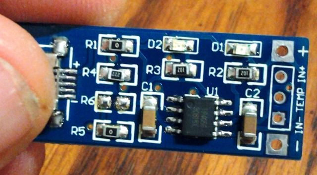
Also gotta be careful with some of the square TP4056 boards [longer rectangle ones seems 0805 standard], the RProg resistor is a 0603, the 0805’s will fit but you have to be a bit more careful on placement
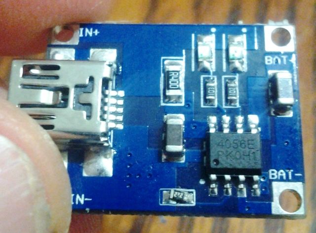
This is the board I changed for fellow board member woolfam, not the most beautiful solder job, but I tested and they too were pushing a clean .53A and .48A respectively with a 222 resistor on RProg
Changed the 122 [1.2K resistor = 1A] to a 222 [2.2K resistor = 500mA~] Tested, was pushing .53A to a 3.6vdc battery out of the USB module into a repaired Xtar MC1 slider housing
I can confirm at 1A charge the TP4056 gets VERY hot, burned my finger when I put it on it to see how it was doing, at 500mA…warm but not leave a mark on my finger.
WarHawk, I see two different “4056” chips. Love how china makes clones of clones. Might want to check the current a few times throughout a charge cycle. Check that the current tapers off at the end & appears to do some kind of cc/cv. Also that it terminates well without trickle charging.
I had an unmarked 4056 clone that was trash. No attempt at cc/cv. Over 4.27v.
Perhaps these “4056” clones should get a separate thread since they are not the chip HKJ tested.
My solar cell arrived yesterday. Got 7 V and 350 ma with direct sun& haze seems to be charging now!!!
I soldered leads to the board and solar cell then attached the wires with alligator clips. Should make it easy to put it back in mini USB 5V.
My board has no logo. Seems to work OK but cuts off around 4.10 V usually.
A US penny will fit on the back without touching any connections for heatsink. I just alligator clipped it. Didn’t seem to need it though. Didn’t sand. Only got up to 550 ma or so on mini usb. Assuming i measured it right, 850ma listed usb oem phone charger.
A friend told me solar runs off IR, which gets blocked by haze. So I might have to keep an eye on V. However I think the board may be controlling V.
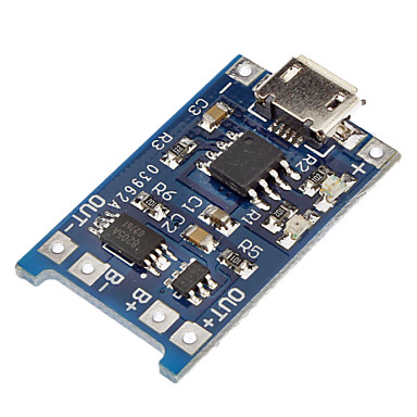
I’ve noticed that MP1405 based boards are offered as widely as TP4056.
It says that they have protection built-in. That might be very useful for small DIY projects. Did anyone here test them. Are they as good as TP4056 based boards?
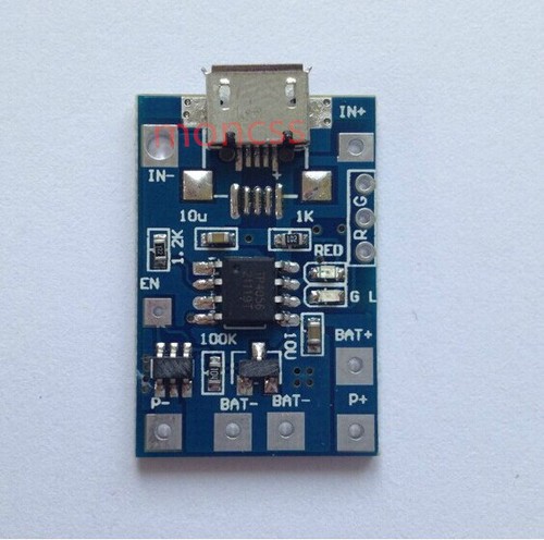
Ordered one of these today:
Only now I’ve noticed that there are two BAT- connections. What for? Also, R and G connections are for external LEDs, right? And what is the EN connection for?
Hello,
I need to know where i can buy the TP4056 as chip only.
I want to integrate it on one of my boards.
I do not need the full populate pcb as it is too big
Any link to buy outside of China ?
I am actually in Canada.
Ebay sellers do not need to apply, due to the facts that they are more expensive than the full assembled PCB.
I bought the full PCB for 0.9USD
I haven’t seen this type of board before, I like the idea of integrating charging and protection in the same board! does someone know what kind of protection does it have? over discharge only? or it also has over current protection? if so, how many amps? (I assume It doesn’t have overcharge, being a charger supposed to stop by itself, but if it has also a separate controller for protection with overcharge too, this is a great find!)
I might have some ideas. How many are you looking to buy?
On second though, I don’t have any bright ideas. I took a quick look at ebay and in the US, you can get them shipped for $0.50USD/chip in lots of 5, or$0.15USD/each for 100. Yeah, they ship from china, but that’s the source.