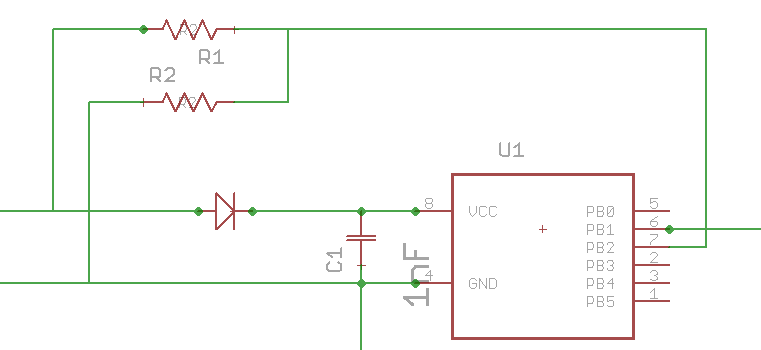
I compiled a list of different values for R1 keeping R2 the same at 4.7k ohms using different forward voltage drops on D1. This is for a Zener mod of drivers and firmware that use 19.1k and 4.7k for R1 and R2.
Assuming that the battery voltage under load trips lvp at 2.8v and that R/(R1+R2) = .1975 for those two values then when the voltage drop across D1 is:
Case #1, .25V pin 7 sees .1975 x (2.8-.25)=.50V
Case #2, .3V pin 7 sees .1975 x (2.8-3)=.494V
Case #3,.35V pin 7 sees .1975 x (2.8-.35)=.484V
Case#4, .4V pin 7 sees .1975 x (2.8-4)=.474V
I went to the mouser catalog and looked up replacement resistors for R1 that would give these same voltages when the battery voltage was 5.6V or (2 x 2.8V).
For D1= .25V, R1= 47.5k ohm
For D1= .3V, R1= 48.7k ohm
For D1=.35V, R1= 49.9k ohm
For D1= .4V, R1= 51K ohm
Mouser has these values in 0805 1% for ~ $.10 each so as soon as I get some decent values for VD1 I’ll order some to try out.
Even at a full charge of 8.4V pin 7 will still see less than 1.1V so I don’t expect to blow any mcu’s however…
I realize that this is somewhat different than what RMM did so I expect this will be all wrong and I’m not encouraging anyone else to try this but just posting what my plans are.