Gotcha!
The protection diode isn’t in this part of the circuit for the Zener mod but to calculate the correct voltage that pin 7 sees normally it no needs to be accounted for. If you were to remove it from a normal 105c then the protection wouldn’t register until the battery was dangerously low.
My point is that you are setting yourself up for a job that will end up needing to be done again in the future. Why bother when we can eliminate the task you asked about (measuring vDrop on the protection diode and changing formulas in the firmware)?
You didn’t start the conversation about a normal 105c, it was about Oshpark boards. If we modify the design to supply the divider with BAT+ instead of hooking the divider up to the protection diode then we’ll simply need to adjust resistor values to achieve the appropriate ratio for the divider. That’s a one time job, changing brands or models of resistor in the future will not have an effect on the voltage supplied to the ADC (unlike changing brand/model of diode). VREF will be constant, unaffected by the diode or absence thereof. Hopefully you see my point now?
EDIT: adding pic for clarity, see below.
I saw your point before and it is my intention to bypass the diode for Zener mods but to correctly figure out what resistors to use I need to be able to account for any diodes being used now. Doing a Zener mod and keeping low voltage detection with any driver that has the diode in front of the divider requires knowing the voltage drop of the diode. Obviously if the diode doesn’t precede the divider then the correct values can be anticipated.
I have not measured the diodes directly, but, when using the DrJ firmwares that blink out the battery voltage, it gives the same number of blinks as the original Nanjg S4 diode. That's only a resolution of 0.1v but it doesn't have to be that close. It's not like a cutoff of 2.8v/cell vs. 2.7v/cell will make a significant difference in actual use. I think nearly all cells get their factory capacity ratings from being run down to 2.75v anyway (some even cheat and run them all the way down to 2.5v).
Sorry, I couldn’t see where you were coming from there. Now it makes sense to me!
I confuse myself sometimes. I should not have mentioned the digicart diode since the S4 is likely the only one I need to worry about but I wanted to solve the general equation before moving to specific examples. CC is quite right about the resolution here but since margin of error is additive I’d like to do what I can to not make it worse. Mainly I’m just stumbling along trying to figure this stuff out and posting my ignorance for all to see. Usually Texaspyro will come and save the day with dry wisdom. I was never shy about asking the stupid question in class.
I think the error factor might be more of an issue using two cells as slight cell imbalance combined with .1v or more error might be an issue. I guess it depends on how far apart the cells are when the combined voltage hits 5.6V.
Do you mind restating, in it’s entirety:
- what you are trying to achieve right now
- what you need in order to accomplish it
:~
In other words “get organized”(thank you Wallace&Grommit)
I will be using a 105C board with the 7135’s removed and the mcu replaced with one flashed for me by Dale.
It will have an Lfpak56 FET since I have some(rated for 100A) and fits the board with no overlap of ground ring. The pins don’t match the 70N02 so I won’t be using an Oshpark board.
Existing 4.7k R2 and new value for R1(somewhere between 47k and 51k).
The 7135 position closest too output traces cut, D1 as the jumper for Vin, a jumper wire from Vout to Vcc.
Voltage divider disconnected from Vcc and jumpered to Vin using current L+ pad or somewhere on the pwm trace after D1.
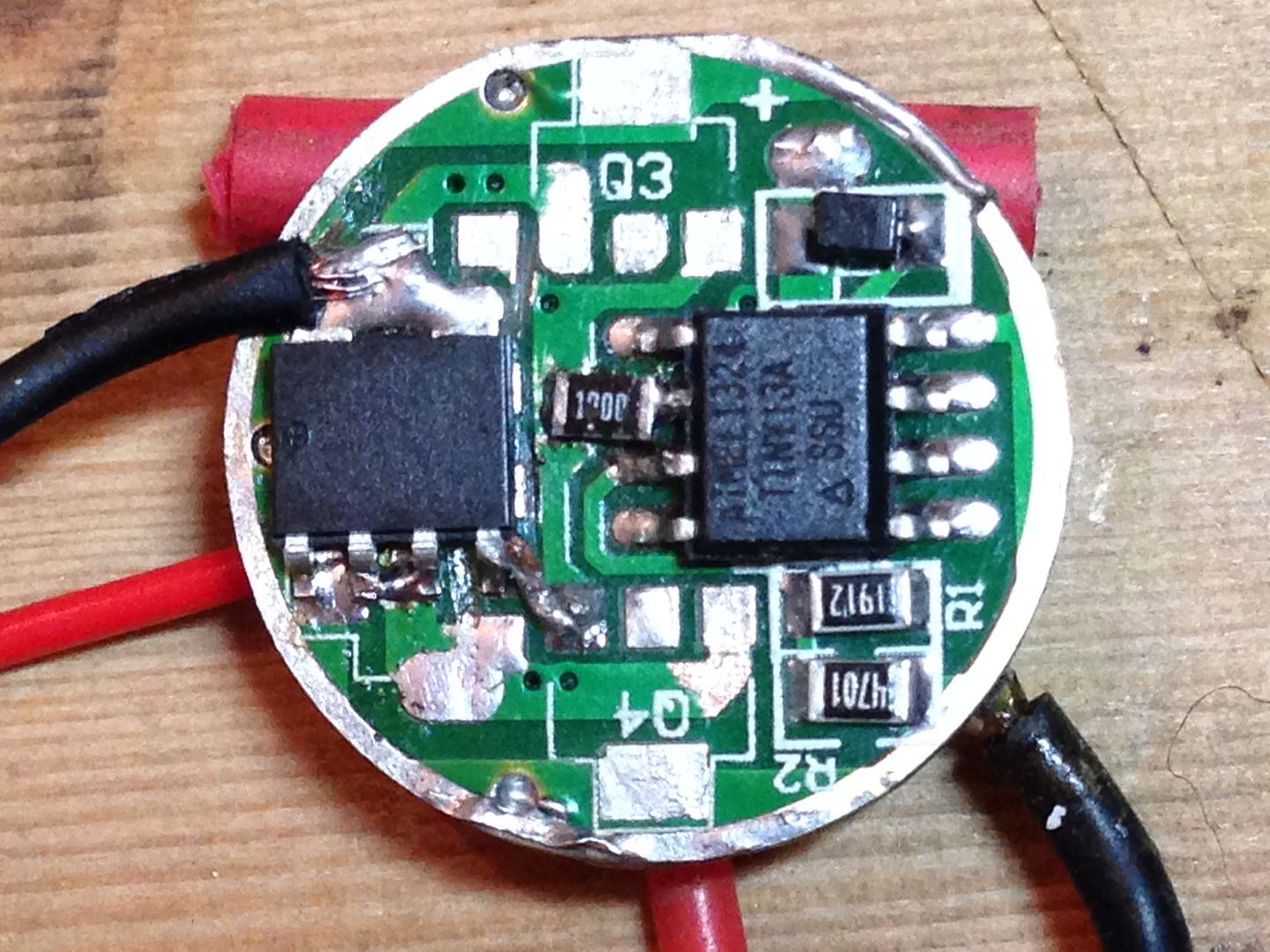
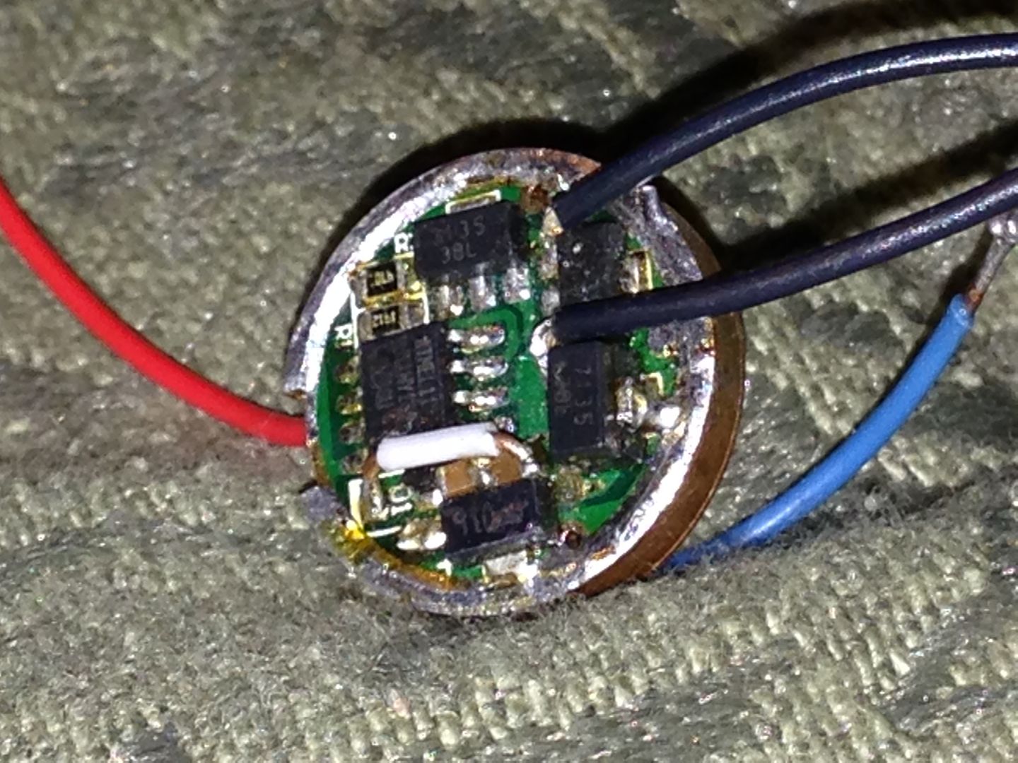
After all the work on the Oshpark boards by others I must be just a glutton for punishment. Here’s a pic of the board I’ll be modifying. Q3 is where I’ll put the voltage regulator and I’m thinking of drilling through the pwm trace for a direct path for L+.
Getting back to the main topic of the thread, if I connect the divider to B+ before the diode I need to know the voltage drop of the diode but if I’m using the same diode and connect the divider after the diode I just use 2.8v per cell to recalculate R1? This doesn’t seem right to me. I think you still need to know the voltage drop across D1 to get the correct value for R1 but wth do I know? Maybe you’re right in that not knowing VD1 won’t give you the exact value of the actual voltage read by pin 7 but will still give you the correct resistance value if you match that offset value. I think I need an Ervin translation. ![]()
Cool. Yeah, you are clearly in it for the pain. With your simple changes I’m sure someone here would be willing to generate a PCB if you had a change of heart.
- You need to keep D1 because LD2981 does not have reverse polarity protection, right?
- I think you’ll need a second fly wire to get from the protected side of the diode (towards the outside of the PCB) back to Vin on the LD2981.
- You’ll need the support caps for LD2981 I suppose, so you’ll either need to keep C1 in place and add an input cap for the LD2981 somewhere or you’ll need to strip C1 and place both input and output caps somewhere for the LD2981.
- In order to use C1 you’ll need to cut both of the other traces leading away from the via - the one that goes to D1 and the on that goes to R1.
- Once you consider your cap needs it seems easiest to me to cut the trace that feeds the divider and use a fly wire to attach the divider to BAT+.
So that looks like 3 fly wires to me, several cut traces, and stacking 1 cap (the input cap) on top of the pins for the LD2981.
This is a mod I worked out originally almost 2 years ago(minus the FET and divider correction in 7135 drivers with higher voltages and yes it requires some caps and jumpers. Here is a pic of how that mod was done. It ran 3 XML’s in series from 12V input. I ended up just stacking the caps on the pins of the regulator. This was before I knew of the MTG (before Gen1) and I never used it because of the lack of low voltage detection. It’s kind of exciting to finally be almost in position to use this idea after so long. 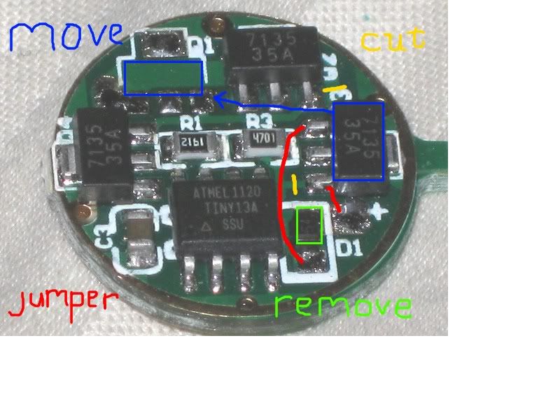
Edit-oops! Here’s a pic with the regulator in place sans caps. It appealed to me because of the sot89 package. 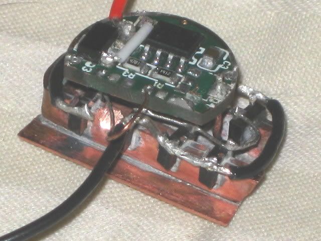
At the time I was also toying with better heat sinking for 7135’s.
Your drawing shows D1 as “remove”. That’s fine, but you’ll have no reverse voltage protection.
You’re still talking about a diode though, so I suppose you plan on putting it back… somewhere?
You seem to have it backwards. With the divider attached like a stock 105c of course you need to know the drop across the diode. That’s why it’s accounted for in our existing firmwares! Once you connect the divider to BAT+ you no longer care about drop across the diode.
The reference voltage produced by your ATtiny13A is completely unaffected by D1 - it will always be 1.0v /-0.1v. (yeah, that’s a/-10% tolerance… eww). The voltage coming out of a divider fed directly from BAT + will be whatever the divider ratio dictates.
Yes, I realized later that I could use D1 as the jumper for the regulator.
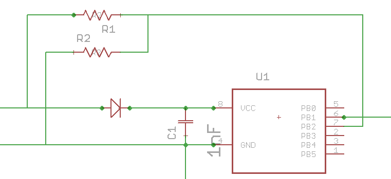
I probably have this all wrong but with the diode dropping .25V and a cell at 2.8V and with R1 and R2 at 19.1k and 4.7k pin 7 will see (2.8-.25)(4700/23800)= .5V
To get low voltage regulation to work I need to be able to show pin 7 - .5V when Vb=5.6V.
If the voltage drop across the diode is some value other than .25v then .5V is the wrong target for the divider.
Do I ignore the diode in the calculation? 2.8 x .1975= .55V.
5.6(4700/R1+4700)=.55
5.6(4700)=.55(R1+4700)=.55R1+.55(4700)
(5.6(4700) - .55(4700))/.55 = R1 = 43155ohms
Using R1 = 43155 and accounting for the same .25v diode drop pin 7 should actually see .5V. Let’s try it.
(5.6-.25)(4700/(43155+4700)=.53V not .5V.
This was assuming the voltage divider was left connected after the diode and the voltage drop across the diode ignored.
Try again with a target of .5V and connecting again after the diode.
(5.35(4700) - .5(4700))/.5=. R1 = 45684 ohms.
And one more before the diode
(5.6(4700) - .5(4700))/.5 = 47940 ohms .
I have the feeling I’ve missed something crucial but at this point I figure I’ll just try some different values for R1 and see what happens but to me it looks like with R2 at 4.7k and
Divider connected after the diode, R1 = ~ 45.7k ohms.
Divider connected before the diode, R1 = 47.9k ohms
Whether you put the divider before or after, I don’t see how the diode can be ignored.
I had some trouble following your post, but let’s wade into this mess:
This is how the stock divider on a 105c works when the battery hits 2.8v:
4700/(19100+4700)*(2.8 - 0.25) = 0.503v
Exactly as expected. Of course, this leaves you in a situation where changing the diode potentially changes the voltage reading. This is what I was commenting on earlier.
In order for a 2s battery LVP to work correctly without the diode we just need change a resistor. Swap the 19.1k for a 48.1k to get 0.498 out of the divider before the diode like this:
4700/(48100+4700)*5.6 = 0.498v
This will cause LVP to kick in at 5.617v
When I say “before” the diode, I mean that the diode is connected between MCU’s VCC and BAT. I consider BAT to be “before” VCC. I think that’s pretty standard phrasing, anyone can feel free to correct me on that though if they know better. Once you have connected Vin for the divider to BAT+ (“before” any diodes or any other things) the diode is no longer part of the calculation for the divider circuit.
I have no idea what makes you think that a diode that isn’t in-circuit with the divider can make a difference, but it simply isn’t true. If you make a complete circuit with a voltage divider (it has Vin, Vout, GND) and the diode isn’t in there… it DOES NOT NEED to be accounted for in your math.
I’ve lost my skills at solving equations, so I don’t do it. I use a solver such as this one: http://www.raltron.com/cust/tools/voltage_divider.asp
It was the first thing we both did to get the .5V we both started with. That’s what I mean by accounting for it. Yes, of course if the divider is tapped into the circuit before the diode then it’s not part of the circuit but to get that .5v we both started from the assumption was a diode drop of .25v and if that is incorrect then the new value of R1 will be incorrect.
My appologies since my intent was to gain a better understanding rather than argue over a misunderstanding. I think we agree but are looking at different ends of the elephant.
Please avoid using phrases of the type “I have no idea what makes you think…” As they are a bit antagonizing and just show that you did not understand me. Just say you don’t understand. Just about everything in your last post was covered above in mine so I don’t think we really disagree. There was a typo between my last calculated value of 47940 and the 47.k. 47.9k and 48.1k aren’t too different.
Here’s another pic of a 105c from back then. I think it was the last one I did and shows the diode turned and used to connect to the input of the voltage regulator. The white wire goes from Vreg out to Vcc and you can see the caps stacked on the regulator pins.
I’ll show a board that’s been cleaned up and has the proper traces cut in a week or two when I get back to this part of the project.
Sorry, I shouldn’t antagonize. Once I read “Whether you put the divider before or after, I don’t see how the diode can be ignored” I became really frustrated with this situation.
Now, upon looking very carefully back over the thread (more than once), I think I’m starting to see where we went wrong. I think you’ve been assuming that I meant to attach an unmodified divider (19.1k / 4.7k) to BAT+ and then use an unmodified firmware. When you kept saying that the diode can’t be ignored, I suppose you meant that the diode makes a difference - when present it reduces voltage and when absent it does not.
If my new understanding of the situation is correct, I’m still at least a little frustrated! When I jumped into the discussion you were already talking about changing resistor values to suit different diodes. So all that needed to be done when you get the divider Vin from BAT+ is to change the resistor values to suit that.
The bottom line remains that if you hook divider Vin to BAT+ and divider GND to BAT- then the diode is not present in the math for the divider.
EDIT: slightly less antigonizing on this post too. ![]()
Nice work squeezing the regulator, 2 caps, and diode all into that tiny space btw. If you hadn’t specifically said that the diode was there I wouldn’t even have seen it.